400G Direct Attach Copper (DAC) has become an important short-reach interconnect option for high-density data centers, AI clusters, HPC systems, and high-speed Ethernet networks. Among the available 400G interfaces, QSFP112 and QSFP-DD are two important form-factor options. Both can provide 400G-class connectivity, but they differ in electrical lane architecture, mechanical design, host compatibility, interoperability, and deployment considerations.
A 400G DAC is an integrated copper cable assembly designed to connect two high-speed network interfaces without separate optical transceivers and fiber patch cords. The cable ends contain pluggable connector assemblies that mate directly with compatible host ports. Passive DACs do not require optical conversion and are normally intended for short-distance links.
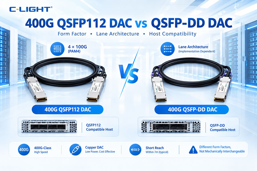
QSFP112 is a 400G pluggable form factor designed around four high-speed electrical lanes. A typical 400G implementation uses four approximately 100G-class PAM4 lanes, often referred to as 400GAUI-4. The form factor keeps a compact QSFP-style mechanical design while supporting the electrical bandwidth required by modern 400G networking.
QSFP-DD, or Quad Small Form-factor Pluggable Double Density, extends the traditional QSFP architecture with additional electrical contacts. Depending on the implementation and generation, 400G QSFP-DD systems can use different lane configurations, including architectures based on eight lower-rate lanes or four higher-rate lanes. Therefore, the exact host electrical interface must always be verified.
The two solutions can both provide 400G connectivity, but a QSFP112 DAC and a QSFP-DD DAC are not mechanically interchangeable. Their host cages, electrical interfaces, lane mapping, management requirements, and supported cable configurations can differ. Selecting the correct DAC requires matching the cable to the complete platform architecture.
The primary difference is the electrical and mechanical design of the host interface. QSFP112 is optimized around four high-speed 100G-class electrical lanes, while QSFP-DD provides a broader electrical interface that can support multiple lane architectures. This distinction affects host compatibility and interoperability even when both products are labeled 400G.
| Feature | 400G QSFP112 DAC | 400G QSFP-DD DAC |
|---|---|---|
| Form Factor | QSFP112 | QSFP-DD |
| Bandwidth | 400G class | 400G class |
| Typical Lane Architecture | 4 × 100G-class | Implementation dependent |
| Signaling | PAM4 | PAM4 |
| Medium | Copper | Copper |
| Connector | QSFP112 | QSFP-DD |
| Reach | Short reach | Short reach |
| Host Cage | QSFP112-compatible | QSFP-DD-compatible |
Lane architecture is particularly important at 400G. QSFP112 commonly uses four electrical lanes at approximately 100G-class signaling rates. QSFP-DD can support different host electrical architectures depending on the system generation. A DAC must be designed for the lane arrangement expected by the host ASIC, switch, NIC, or router.
Both 400G architectures commonly use PAM4 signaling. PAM4 has four amplitude levels and transmits two bits per symbol. Compared with NRZ, it allows substantially higher data throughput at a given symbol rate, but it also places greater demands on electrical channel quality, equalization, and error correction.
400GAUI-4 is a four-lane electrical interface used by many 400G implementations. Each lane carries approximately 100G-class signaling using PAM4. QSFP112 is strongly associated with this four-lane architecture, making lane compatibility a key factor when selecting a QSFP112 DAC.
QSFP-DD 400G implementations can use different electrical lane arrangements depending on the host platform and generation. Older designs may use eight lower-rate lanes, while newer architectures may use four 100G-class electrical lanes. Therefore, “QSFP-DD 400G” alone does not provide enough information to determine cable compatibility.
QSFP112 and QSFP-DD are related to the QSFP family but use different connector and cage implementations. The host equipment determines which mechanical interface is supported. A DAC connector designed for QSFP112 should not be treated as a direct replacement for a QSFP-DD connector.
The switch, NIC, router, server adapter, or other device must have the appropriate cage and electrical interface. Before purchasing a DAC, confirm the exact host port type, supported cable family, electrical signaling mode, and vendor compatibility list.
No. Although the two form factors belong to the broader QSFP ecosystem and may appear similar, they are not simply interchangeable modules. Mechanical fit, pin assignment, lane mapping, management, and electrical signaling must all be considered.
A QSFP112 port is generally designed around four high-speed electrical lanes. This approach provides a compact path to 400G and aligns well with modern 400G optical and copper interconnect architectures.
QSFP-DD provides a higher contact density and was designed to support multiple generations of high-speed networking. This flexibility allows QSFP-DD platforms to support different electrical lane rates and network speeds, depending on the host implementation.
400G DACs are intended for short-reach applications. Actual cable lengths vary by conductor design, gauge, passive or active architecture, connector quality, and host electrical channel. The maximum supported length should always be taken from the specific cable specification.
Electrical loss increases with frequency and cable length. At 400G, insertion loss, return loss, crosstalk, reflections, and inter-symbol interference can significantly affect signal quality. Passive copper therefore becomes increasingly difficult to use as reach increases.
A passive DAC provides a direct copper path without active signal-conditioning electronics inside the cable assembly. It is attractive for low-power, short-distance connections where the combined host and cable channel remains within the required electrical limits.
An active electrical cable can include components that compensate or condition the electrical signal. These cables may provide greater reach than passive DACs in certain applications, but they have additional power and compatibility requirements and should not be treated as electrically identical to passive DACs.
QSFP112 DACs may be available as direct 400G-to-400G cables or breakout assemblies. A direct cable is commonly used for switch-to-switch or switch-to-NIC connections, while breakout configurations can connect a 400G interface to lower-speed ports where the host platform supports the required mode.
QSFP-DD DACs can also be configured for direct 400G connections and breakout architectures. Supported configurations depend on the electrical lane architecture and the host platform. The same cable form factor can therefore be associated with different networking modes.
400G connectivity can be broken into lower-rate interfaces such as 2 × 200G or 4 × 100G when supported by the host system. Breakout is useful when connecting different network generations or building multi-speed AI and data center fabrics.
Because QSFP112 commonly uses four high-speed lanes, the host platform can sometimes map individual lanes or lane groups to lower-speed interfaces. The exact breakout options depend on the host ASIC, NIC, firmware, and supported electrical standards.
QSFP-DD has historically been used for a wide range of breakout configurations. Depending on the system architecture, an individual 400G port may connect to multiple lower-speed interfaces. However, the cable lane mapping must correspond exactly to the host configuration.
Signal integrity is one of the most important engineering considerations for 400G DACs. The effective electrical channel includes the host ASIC or SerDes, PCB traces, connectors, the DAC, and the receiving interface. Any weak point in this chain can reduce eye opening and increase error rates.
Insertion loss increases with frequency and cable length. High-speed 400G systems therefore require controlled cable construction and carefully designed connectors. A DAC that works reliably at a short length cannot automatically be assumed to work at a longer length.
Multiple high-speed copper lanes can interfere with one another through near-end and far-end crosstalk. Cable geometry, shielding, conductor spacing, connector design, and equalization all influence the final signal performance.
Forward Error Correction can improve error tolerance in high-speed links. FEC implementation may reside primarily in the host system, depending on the architecture. The DAC itself should therefore be evaluated together with the switch or NIC's FEC configuration rather than independently.
Passive copper provides a direct electrical path and avoids optical conversion. This makes DAC attractive for short-reach applications where low link complexity and low latency are important. The actual end-to-end latency, however, also depends on the host ASIC, SerDes, NIC, and network architecture.
Passive DACs generally have very low cable-level power consumption because they do not contain optical lasers, receivers, or conventional optical DSPs. However, the host SerDes and switching ASIC still consume power to drive the high-speed electrical channel.
Even when the DAC itself is passive, the host interface contributes to system heat. High-speed SerDes, ASICs, connectors, and adjacent ports can increase thermal density. QSFP112 and QSFP-DD platforms must therefore be evaluated according to the actual host thermal design.
High-speed DAC cables may use relatively large conductors to control electrical loss. Larger conductors can improve high-frequency performance but may increase cable diameter and reduce flexibility. This affects cable management in high-density racks.
AI clusters may contain hundreds or thousands of high-speed interconnects. Thick DAC assemblies can create significant cable-management challenges if many are installed in a concentrated area. Bend radius, connector access, airflow, and cable routing should be included in the physical design.
400G DACs are increasingly relevant to AI and HPC environments where large numbers of servers, GPUs, NICs, and switches must exchange data over short distances. DAC can reduce the number of optical components in these very short links.
Where a GPU server or high-speed NIC is located close to the network switch, a 400G DAC can provide a direct high-bandwidth electrical connection. This approach can simplify cabling and avoid separate optical transceiver and fiber assemblies.
400G DACs can connect adjacent or closely positioned switches where the physical distance remains within the specified electrical reach. As the distance increases, AOC or optical transceivers become more practical.
Both QSFP112 and QSFP-DD 400G DACs can be used in high-speed Ethernet environments when supported by the host platform. Applications include leaf-spine networks, aggregation systems, switch-to-NIC links, and high-density server connectivity.
High-performance computing and AI networks place strong demands on bandwidth, latency, congestion handling, and port density. Compatible 400G DACs can be used for short connections in these environments, but the cable must match the specific switch and adapter architecture.
| Parameter | 400G DAC | 400G AOC |
|---|---|---|
| Medium | Copper | Optical fiber |
| Typical Reach | Very short | Longer short-reach |
| Optical Conversion | No | Yes |
| Cable Flexibility | Usually lower | Usually higher |
| Power | Very low for passive versions | Active electronics required |
| EMI Sensitivity | Electrical considerations | Low through optical transmission |
A DAC combines the cable and connector assemblies into one product, making it convenient for short links. Optical transceivers use separate fiber cabling and can support a much wider range of distances. The choice depends primarily on distance, cabling architecture, power, and host compatibility.
Compatibility should be checked at four levels: mechanical, electrical, management, and software. The connector must match the cage, the lane architecture must match the host, the identification information must be accepted by the platform, and the firmware must support the selected operating mode.
Modern switches and NICs may read identification data from the cable assembly before enabling a link. Vendor coding, part-number information, cable characteristics, and supported operating parameters can affect acceptance. Qualified coding should therefore be confirmed before deployment.
High-speed pluggable modules increasingly use standardized management structures. However, passive DACs and active electrical cables may expose different management information depending on the implementation. Management support should be verified against the host platform rather than assumed from the form factor.
Modern switch ASICs define the electrical interface available at each port. A host may support 400GAUI-4, an eight-lane electrical architecture, or another configuration. The DAC must correspond to the actual electrical interface exposed by the ASIC and retimer or SerDes path.
400G NICs can use different physical and electrical implementations. Before selecting a QSFP112 or QSFP-DD DAC, verify the NIC vendor's supported cable list, required lane rate, breakout support, FEC requirements, and maximum supported cable length.
Interoperability testing should include both endpoints and the cable. Test link establishment, port mode, lane status, FEC counters, error rates, temperature, sustained traffic, breakout behavior, and management information. This is particularly important when connecting equipment from different vendors.
A QSFP112 DAC is appropriate when the host equipment provides a QSFP112-compatible port and uses the corresponding four-lane high-speed electrical architecture. It is particularly relevant for compact 400G platforms built around 100G-class PAM4 lanes.
A QSFP-DD DAC is appropriate when the host equipment uses a QSFP-DD cage and supports the selected electrical architecture. QSFP-DD may provide broader platform flexibility, but the exact lane configuration must be confirmed before deployment.
QSFP112 DAC is practical when the deployment uses compatible QSFP112 ports, requires a short 400G electrical link, and benefits from a compact four-lane architecture. It can be useful in newer 400G Ethernet and AI networking platforms.
QSFP-DD DAC is practical when the network already uses QSFP-DD equipment or requires the ecosystem flexibility associated with the QSFP-DD platform. It can support a range of 400G implementations depending on the host electrical design.
Neither QSFP112 DAC nor QSFP-DD DAC is intended to replace long-reach optical connectivity. When a link extends beyond the supported electrical cable distance, the network should transition to AOC or optical transceiver solutions designed for the required reach.
Common mistakes include selecting a cable only by the 400G label, ignoring the host cage, assuming QSFP112 and QSFP-DD are interchangeable, overlooking electrical lane mapping, exceeding the cable length specification, using an unsupported breakout mode, or failing to verify vendor coding.
When a 400G DAC fails to establish a link, first verify the physical form factor and host port type. Then check cable identification, electrical lane configuration, breakout mode, FEC settings, firmware, cable length, and remote-end compatibility. Host diagnostics and FEC counters can help identify lane-level problems.
Before ordering a 400G DAC, verify host port type, form factor, electrical lane architecture, PAM4 lane rate, passive or active design, cable length, cable gauge, breakout requirements, FEC configuration, vendor coding, operating temperature, cable routing requirements, and interoperability.
| Parameter | 400G QSFP112 DAC | 400G QSFP-DD DAC |
|---|---|---|
| Form Factor | QSFP112 | QSFP-DD |
| Nominal Speed | 400G | 400G |
| Typical PAM4 Architecture | 4 × 100G-class lanes | 4 × 100G-class or 8 × lower-rate lanes, depending on implementation |
| Medium | Copper | Copper |
| Typical Use | 400G short-reach links | 400G short-reach links |
| Host Interface | QSFP112 cage | QSFP-DD cage |
| Passive DAC | Available | Available |
| Breakout | Platform dependent | Platform dependent |
| Reach | Short reach | Short reach |
| Interchangeability | Not directly interchangeable | Not directly interchangeable |
The move toward 800G and 1.6T increases pressure on electrical channel design, connector performance, thermal density, and SerDes capability. A 400G DAC deployment should therefore be considered as part of a broader network migration strategy rather than as an isolated cable decision.
400G QSFP112 DAC and 400G QSFP-DD DAC both provide high-speed short-reach copper connectivity, but they are designed for different host interfaces and electrical architectures. QSFP112 commonly uses four 100G-class PAM4 lanes and is closely aligned with 400GAUI-4 implementations. QSFP-DD provides a broader electrical interface that can support different 400G lane configurations depending on the platform. The most important selection criteria are the host cage, electrical lane architecture, cable length, passive or active design, breakout mode, FEC, power and thermal conditions, vendor coding, and interoperability. For AI data centers, HPC systems, and 400G Ethernet networks, the DAC should always be selected according to the complete host-to-host electrical link rather than the 400G label alone.
For any questions, please contact us by email or WhatsApp.
Email: sales@c-light.com
WhatsApp: +86 132 6656 7067