



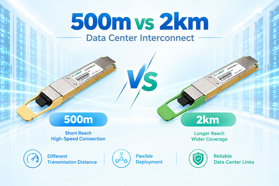
Data center interconnects do not all span the same distance. Some facilities are close enough to connect over a few hundred meters, while others require optical links extending several kilometers. A 500m DCI and a 2km DCI may use the same basic networking principles, but their optical requirements can be quite different.
The additional distance affects more than the length of the fiber cable. It can influence the choice of transceiver, fiber type, optical budget, cabling architecture, link margin, power consumption and total deployment cost. Planning these factors together helps ensure that the DCI link has enough capacity and reach without adding unnecessary optical complexity.
| Feature | 500m DCI | 2km DCI |
|---|---|---|
| Link Distance | Up to about 500m | Up to about 2km |
| Typical Environment | Nearby data halls, buildings or campus facilities | Separated buildings or data center sites |
| Fiber | Multimode or single-mode depending on the optical solution | Commonly single-mode fiber |
| Optical Budget | Lower | Higher |
| Optical Architecture | Often optimized for short-reach operation | Designed for greater transmission margin |
| Power | Often lower | May be higher |
| Cost | Generally lower | Generally higher |
| Deployment Flexibility | Best suited to compact DCI routes | Provides more reach for longer site connections |
A 500m DCI is an optical connection between data center network locations where the complete fiber route is within approximately 500 meters.
This type of connection may be used between nearby data halls, adjacent buildings, or separate data center facilities within the same campus or complex. The relatively short distance makes it possible to use optical solutions designed for short or moderate reach, depending on the data rate and fiber infrastructure.
A 2km DCI connects data center network locations over an optical path extending up to approximately 2 kilometers.
The longer route can be useful when multiple facilities are distributed across a larger campus or when separate data center buildings are located farther apart. Compared with a 500m connection, the 2km link needs to account for additional fiber attenuation and potentially more connection points.
Adding 1.5 kilometers to the optical route may seem simple from a cabling perspective, but the optical signal also has to travel through more fiber and potentially more patching infrastructure.
As distance increases, the available optical margin becomes more important. The transceiver therefore needs to be selected according to the full link budget rather than just the nominal cable length.
Fiber selection depends on the transceiver and DCI architecture. Shorter 500m links can use multimode or single-mode fiber depending on the required data rate and optical design.
For 2km DCI, single-mode fiber is commonly used because it is better suited to longer optical paths. This can also provide more flexibility when the network is expected to expand beyond the original distance.
The transceiver specification should always be checked before selecting the installed fiber type.
The optical budget is a central factor when comparing the two DCI distances.
A simplified relationship is:
Maximum Allowable Loss = Transmitter Output Power − Receiver Sensitivity
A 500m route normally consumes less optical budget than a 2km route when comparable fiber and connection conditions are used. A 2km DCI therefore requires more attention to transmitter power, receiver sensitivity and total system loss.
DCI planning should include more than the fiber itself. Optical connectors, patch panels, adapters and splices can all contribute additional loss.
The total loss can be represented as:
Total System Loss = Fiber Loss + Connector Loss + Splice Loss + Passive Device Loss + Other Optical Losses
This is especially relevant when the DCI route contains multiple cross-connect locations between the two data centers.
The optical module should match both the reach and the required network speed. A 500m DCI may be supported by short-reach optical architectures, while a 2km connection can require a module with a larger optical budget.
At higher Ethernet data rates, the difference can also involve lane architecture, wavelength configuration, DSP functionality and FEC. Reach, data rate and optical technology should therefore be considered together.
Power consumption is important in DCI environments because optical modules are deployed in large numbers across switches and routers.
A 500m solution may use a simpler optical architecture and can therefore offer lower power in some product families. A 2km module may require higher-performance optical components, although actual power depends on the specific transceiver design.
For high-density DCI equipment, even small per-port power differences can affect the overall thermal load.
500m DCI can often be implemented with lower-cost optical modules and simpler cabling because the reach requirement is less demanding.
A 2km DCI may require higher-rated transceivers and single-mode infrastructure, which can increase the initial optical cost. However, the total project cost should also consider existing fiber availability, patching requirements and future network expansion.
| Scenario | 500m DCI Characteristics |
|---|---|
| Adjacent Data Buildings | Useful when the actual fiber route remains short |
| Same-Campus Data Centers | Suitable for closely located facilities |
| Data Hall Interconnect | Practical for compact facility layouts |
| Short DCI | Can minimize optical cost and power requirements |
| Scenario | 2km DCI Characteristics |
|---|---|
| Separated Data Center Buildings | Provides additional reach between facilities |
| Larger Data Center Campus | Useful when buildings are more widely distributed |
| Extended DCI | Provides greater optical distance capability |
| Future Network Expansion | Can accommodate longer cable routes when properly planned |
DCI links should not be designed exactly at the nominal maximum distance without considering additional losses. The actual route may include unexpected cable slack, extra patching or future modifications.
A practical design keeps sufficient optical margin after accounting for fiber attenuation, connectors and other losses. This gives the link more tolerance to real-world installation conditions.
In many cases, a 2km-rated optical transceiver can be used on a shorter 500m link when the wavelength, fiber, connector configuration and host interface are compatible.
However, the extra reach may not provide a useful benefit. A higher-rated module can increase the cost and, depending on the design, the power consumption.
A 500m-rated optical module should not be assumed to support a 2km DCI. Its optical budget may not be sufficient to overcome the additional fiber and connection losses.
Using a module beyond its specified reach can leave insufficient link margin and reduce network reliability. The manufacturer's rated distance should therefore be treated as a design limit.
| DCI Requirement | Selection Consideration |
|---|---|
| Actual route below 500m | A 500m-class solution may be sufficient |
| Route close to 500m | Calculate the complete loss budget before final selection |
| Route between 500m and 2km | Evaluate a 2km-class optical solution |
| Existing multimode infrastructure | Confirm that the selected transceiver supports the installed fiber |
| New single-mode DCI infrastructure | Consider long-term reach and future expansion requirements |
| High-density switches | Compare module power and thermal characteristics |
Distance is only one part of an interconnect design. Data rate, Ethernet standard, transceiver form factor, fiber type, wavelength, optical budget, connector count and equipment compatibility all need to be verified.
Network operators should also consider redundancy and route diversity. Two optical connections may have the same nominal length while following different physical paths with very different levels of fiber and infrastructure risk.
A 500m DCI and a 2km DCI can serve similar networking purposes, but their optical requirements are different. The shorter connection can use a simpler and potentially more economical optical design, while the 2km connection requires greater attention to fiber selection, optical budget and link margin.
For compact data center campuses, 500m optics can be appropriate when the actual route remains within the specified reach. For longer inter-building or campus DCI, 2km-class optics provide additional distance capability and may offer greater deployment flexibility.
The final choice should be based on the real fiber route, total optical loss, required margin, data rate, fiber infrastructure, transceiver compatibility and future expansion plans.
For any questions, please contact us by email or WhatsApp.
Email: sales@c-light.com
WhatsApp: +86 132 6656 7067
