



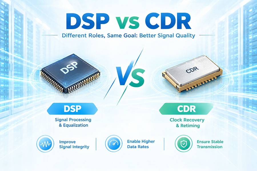
Digital Signal Processing (DSP) and Clock and Data Recovery (CDR) are two important technologies used in high-speed optical communication systems. They both help maintain signal integrity and recover reliable data, but they perform different functions.
CDR primarily extracts timing information from an incoming data stream and uses that timing to sample or retime the signal correctly. DSP performs a much broader range of digital signal-processing operations, including equalization, signal conditioning, impairment compensation, lane processing and, in some architectures, FEC.
Modern high-speed optical transceivers can use CDR, DSP or an integrated architecture that combines CDR functions with a more comprehensive DSP. Understanding the difference is particularly important for 400G, 800G and emerging 1.6T optical modules.
DSP stands for Digital Signal Processor or Digital Signal Processing, depending on the context.
In optical communication, a DSP is a high-speed processing device that digitally analyzes and modifies communication signals to improve signal quality and recover transmitted information.
A DSP can perform multiple processing functions rather than focusing on one specific signal-recovery task.
CDR stands for Clock and Data Recovery.
CDR extracts timing information embedded in an incoming data stream and uses that timing to determine when the receiver should sample the data.
Reliable timing recovery is essential because high-speed serial data normally does not carry a separate clock signal alongside the data.
| Feature | DSP | CDR |
|---|---|---|
| Full Name | Digital Signal Processor / Digital Signal Processing | Clock and Data Recovery |
| Primary Function | Broad signal processing | Timing and data recovery |
| Timing Recovery | Can include it | Core function |
| Equalization | Yes | Limited or architecture dependent |
| FEC | May be integrated | Normally not the primary function |
| Signal Compensation | Extensive | Focused primarily on timing and retiming |
| Complexity | Higher | Lower in many implementations |
| Power | Generally higher | Generally lower |
| Latency | Can be higher | Usually lower |
| Typical Use | High-speed optical modules | Retimers, SerDes and optical modules |
The simplest way to understand the difference is to think of CDR as a specialized timing-recovery function and DSP as a broader signal-processing platform.
CDR answers the question: "When should the receiver sample this signal?"
DSP can address a much wider set of questions, such as how to compensate for channel loss, reduce inter-symbol interference, recover signal levels and process transmission errors.
High-speed serial links normally transmit data without a separate clock line.
The receiver must reconstruct the clock from the transitions in the incoming data stream.
CDR performs this timing recovery so the receiver can sample the signal at appropriate points.
As data rates increase, the signal is affected by electrical and optical impairments.
These can include insertion loss, inter-symbol interference, reflections, crosstalk, jitter, bandwidth limitations and other distortions.
A DSP can digitally compensate for many of these impairments.
CDR and DSP should not be treated as completely interchangeable terms.
CDR describes a specific signal-recovery function, while DSP describes a broader processing architecture.
A DSP can contain or work together with a CDR function, but a CDR does not automatically provide the full capabilities of a modern optical DSP.
Yes.
Many modern high-speed signal-processing architectures integrate timing recovery with other digital processing functions.
In such designs, CDR can be considered one part of the larger signal-processing chain.
Yes.
A CDR can be implemented as a dedicated timing-recovery circuit without providing the complete set of equalization, FEC and signal-processing functions associated with a full DSP.
This approach can reduce complexity, power consumption and latency for suitable applications.
| Function | DSP | CDR |
|---|---|---|
| Clock Recovery | Can support | Core function |
| Data Recovery | Yes | Yes |
| Equalization | Yes | Architecture dependent |
| FFE | Yes | Not normally the main role |
| DFE | Yes | Not normally the main role |
| Digital Predistortion | Possible | No |
| FEC | Possible | No |
| Lane Processing | Possible | Limited |
A simplified CDR system monitors transitions in an incoming serial data stream and estimates the embedded clock timing.
The recovered clock is then used to sample the signal near the center of the data eye.
The exact implementation can use analog, digital or mixed-signal circuitry.
Clock recovery is the process of reconstructing timing information from a signal that does not carry a separate clock channel.
The recovered timing must track the incoming data closely enough to ensure reliable symbol decisions.
Once the appropriate sampling timing has been established, the receiver can make decisions about the transmitted data.
CDR therefore supports both clock recovery and the accurate sampling required for data recovery.
The receiver should ideally sample the signal near the center of the eye where the vertical and horizontal margins are greatest.
CDR helps place the sampling clock at an appropriate position relative to the incoming data.
An eye diagram provides a visual representation of signal quality.
The horizontal opening represents timing margin, while the vertical opening represents amplitude margin.
CDR primarily addresses the timing aspect of the signal.
Jitter represents variation in the timing of signal transitions.
CDR tracks the incoming signal timing and helps maintain an appropriate sampling phase.
Different CDR architectures have different tolerance to various types of jitter.
The transmitter and receiver clocks may operate with slightly different frequencies.
CDR continuously tracks the incoming signal so that the recovered clock remains aligned with the received data.
Many CDR architectures use a phase-locked loop or related timing-recovery mechanism.
The loop adjusts the recovered clock according to the phase relationship between the incoming data transitions and the local timing reference.
The exact circuit architecture varies by device and application.
Some high-speed CDR architectures use phase interpolation to adjust the sampling phase.
This allows the receiver to position its sampling point more precisely within the data eye.
Equalization is one of the most important functions that distinguishes DSP from basic CDR.
Equalizers compensate for frequency-dependent signal loss and distortion introduced by the electrical channel.
This can significantly improve signal recovery at high data rates.
FFE stands for Feed-Forward Equalizer.
FFE applies weighted signal taps to compensate for channel distortion.
It can be implemented in transmitters or receivers depending on the architecture.
DFE stands for Decision Feedback Equalizer.
DFE uses previous symbol decisions to compensate for inter-symbol interference in the received signal.
This is a more advanced signal-processing function than basic clock recovery.
CTLE stands for Continuous-Time Linear Equalizer.
It provides frequency-dependent gain to compensate for high-frequency channel attenuation.
CTLE may operate before or together with digital equalization in a high-speed receiver.
| Function | CDR | Equalization |
|---|---|---|
| Recover Timing | Yes | No |
| Compensate Channel Loss | Not the primary role | Yes |
| Reduce ISI | Limited | Yes |
| Improve Sampling Phase | Yes | Indirectly |
| Signal Amplitude Correction | Limited | Yes |
PAM4 uses four amplitude levels and carries two bits per symbol.
Because the eye openings are smaller than those of a comparable NRZ signal, PAM4 is more sensitive to noise and distortion.
DSP can help compensate for these impairments.
The receiver must distinguish four different amplitude levels rather than two.
Smaller differences between adjacent levels make the signal more sensitive to noise, crosstalk and channel distortion.
Equalization and other signal-processing techniques therefore become important in high-speed PAM4 systems.
CDR can still be used in PAM4 systems because the receiver must recover timing from the incoming multi-level data signal.
However, timing recovery alone is not sufficient to address all of the signal-processing challenges associated with high-speed PAM4.
| Requirement | DSP | CDR |
|---|---|---|
| Timing Recovery | Possible | Core Function |
| Multi-Level Equalization | Yes | Limited |
| ISI Compensation | Yes | Limited |
| Signal Recovery | Yes | Yes |
| FEC Integration | Possible | Generally no |
FEC stands for Forward Error Correction.
FEC adds redundant information that allows the receiver to detect and correct certain transmission errors.
Some optical DSPs integrate FEC encoding and decoding into the same device.
CDR itself is not an error-correction mechanism.
A receiver can use CDR to recover the timing of the signal and then use FEC elsewhere in the processing chain to correct errors.
These functions should therefore be treated separately.
Pre-FEC BER is the bit-error rate measured before forward error correction.
DSP-based equalization and signal processing can help reduce the raw error rate before the FEC decoder receives the data.
Post-FEC BER represents the residual error rate after FEC processing.
The DSP may contribute to the signal quality entering the FEC decoder, but the final post-FEC performance depends on the entire receiver chain.
A simplified CDR-based link can be represented as:
Electrical Signal → CDR → Recovered Data.
A more complex DSP-based architecture can be represented as:
Electrical Signal → ADC or High-Speed Receiver → DSP → Equalization → Clock/Data Recovery → FEC → Recovered Data.
The actual architecture varies by device and application.
A simplified DSP-based optical transceiver can be represented as:
Host ASIC → Electrical Interface → DSP → Driver → Laser or Modulator → Fiber.
On the receive side:
Fiber → Photodetector → TIA → DSP → Electrical Interface → Host ASIC.
CDR can be located inside the optical module, integrated into the DSP or implemented in the host SerDes.
The location depends on the system architecture and the division of signal-processing functions between the host and module.
In conventional DSP-based optical transceivers, the DSP is located inside the module.
The module uses it to process signals between the host electrical interface and the optical engine.
In other architectures, some or all processing functions can be moved into the host system.
On the transmit side, a DSP can process the electrical data before it reaches the laser driver or optical modulator.
Possible functions include transmit equalization, pre-emphasis, digital predistortion, lane processing and FEC encoding.
On the receive side, a DSP can process the electrical signal after the TIA or analog front end.
Possible functions include equalization, clock recovery, signal reconstruction, FEC decoding and diagnostic processing.
Transmit-side retiming can be used to clean up timing before data is sent to the next section of the link.
Some devices therefore contain transmit-side clocking and retiming functions in addition to receive-side CDR.
The receive-side CDR monitors incoming data and recovers the embedded clock.
The recovered clock is then used to sample or retime the data for subsequent processing.
A retimer recovers a high-speed signal and retransmits it with improved timing and signal quality.
A DSP can perform retiming but also provides much broader signal-processing functions.
Therefore, a DSP can be more functionally comprehensive than a dedicated retimer.
CDR is primarily a timing-recovery function.
A retimer generally performs timing recovery and then retransmits the recovered data, often with additional signal conditioning.
Therefore, CDR and retimer are related but not identical concepts.
| Feature | DSP | Retimer |
|---|---|---|
| Clock Recovery | Possible | Yes |
| Equalization | Advanced | Yes, depending on design |
| FEC | Possible | Usually not the primary function |
| Digital Processing | Extensive | More limited |
| Complexity | Higher | Lower in many implementations |
A full DSP performs substantially more processing than a basic CDR and therefore generally requires more power.
The actual difference depends on semiconductor process, operating rate, number of channels, integrated functions and implementation.
Power becomes especially important in 800G and 1.6T optical modules.
DSP processing can introduce additional pipeline and algorithmic latency.
CDR-based retiming generally requires less processing and can therefore achieve lower latency in suitable implementations.
Actual latency depends on the complete device architecture.
Higher power consumption produces greater thermal load.
Because DSPs perform significantly more processing than dedicated CDR circuits, they can contribute more heat within an optical module.
Thermal management is therefore closely connected to signal-processing architecture.
DSP devices are generally more complex than dedicated CDR solutions.
The additional processing capability can increase chip complexity and module cost.
However, a DSP can replace several separate signal-processing functions, so total system cost must be evaluated at the architecture level.
| Category | DSP-Based Module | CDR-Based Module |
|---|---|---|
| Signal Processing | Extensive | Focused |
| Equalization | Advanced | Limited or separate |
| FEC | May be integrated | Usually separate |
| Power | Higher | Lower in many designs |
| Latency | Higher | Lower in many designs |
| Architecture | More complex | More compact |
100G optical modules can use different architectures depending on the optical standard, host interface and transmission distance.
Some designs use relatively simple retiming or CDR functions, while other modules use more sophisticated DSP architectures.
The actual implementation must be determined from the module specification.
CDR remains useful in 100G applications because high-speed serial data requires accurate clock recovery.
Depending on the implementation, CDR can be integrated into a retimer, SerDes or larger signal-processing device.
At 200G, higher-speed PAM4 signaling creates greater requirements for signal equalization and recovery.
DSP-based architectures become increasingly useful for managing these higher-speed electrical channels.
400G optical transceivers commonly use multiple high-speed PAM4 lanes.
DSPs can provide equalization, lane management, signal recovery and FEC-related functions depending on the module design.
CDR functions can still be important in 400G modules because the receiver must recover timing from high-speed serial data.
In many architectures, CDR functions are integrated into larger DSP or SerDes devices rather than implemented as a completely separate chip.
800G modules use extremely high-speed electrical and optical signaling.
DSPs can provide signal conditioning, equalization, clock recovery, lane processing and FEC support where implemented.
This makes DSP technology important in many 800G module architectures.
CDR remains a fundamental timing function in 800G systems.
However, the increasingly complex PAM4 signal-processing requirements often require functions beyond basic clock and data recovery.
As a result, CDR may be implemented as part of a larger DSP or SerDes architecture.
1.6T optical interfaces use higher per-lane signaling rates and place greater demands on electrical channel performance.
Advanced DSP architectures can provide the equalization and signal-processing capabilities required by these high-speed links.
Power efficiency becomes an increasingly important constraint.
At 1.6T, timing recovery remains essential, but a simple standalone CDR cannot address all of the signal impairments associated with extremely high-speed PAM4 transmission.
More comprehensive signal-processing architectures are therefore increasingly important.
| Generation | Typical Signaling Class | Signal Processing Requirement |
|---|---|---|
| 100G | 25G-class or other architectures | CDR or DSP depending on implementation |
| 200G | 50G-class PAM4 | More equalization required |
| 400G | 100G-class PAM4 | Advanced DSP increasingly common |
| 800G | 100G-class or higher PAM4 architectures | Strong signal-processing requirements |
| 1.6T | 200G-class PAM4 | Very demanding equalization and timing recovery |
Signal integrity is affected by the complete electrical and optical channel.
CDR mainly addresses timing recovery, while DSP can address timing and amplitude-related impairments simultaneously.
This broader processing capability becomes more important as channel loss and signaling rate increase.
Inter-symbol interference occurs when one symbol affects neighboring symbols due to bandwidth limitations and channel distortion.
CDR does not fundamentally remove ISI.
DSP-based equalization can actively compensate for ISI and restore a more usable waveform.
Crosstalk occurs when signals on adjacent channels interfere with each other.
DSP can incorporate algorithms that compensate for certain forms of crosstalk and channel interaction.
CDR primarily focuses on maintaining correct timing and does not provide the same level of multi-channel compensation.
Impedance discontinuities can create reflections in high-speed electrical channels.
Reflections can distort the waveform and reduce the available eye opening.
Advanced DSP architectures can include reflection-aware equalization or cancellation techniques in suitable implementations.
Both DSP and CDR architectures can process timing-related impairments, but CDR has a direct focus on timing recovery.
DSP can combine timing recovery with additional equalization and signal-processing functions.
This allows a more complete approach to signal reconstruction.
Signal processing can help extend the usable electrical and optical reach of a transceiver.
DSP provides a broader set of tools for compensating channel impairments, while CDR primarily restores timing and retimes the data.
Longer or more challenging links therefore tend to benefit from more comprehensive signal processing.
Direct-detection optical modules convert received optical power into an electrical signal.
DSP can then process that electrical signal to compensate for distortions and recover data.
CDR can be used to recover the timing of the resulting electrical waveform.
Coherent optical systems rely heavily on DSP.
Coherent receivers must process amplitude and phase information and compensate for effects such as chromatic dispersion and polarization-related impairments.
CDR alone is not sufficient for this class of signal processing.
| Function | Coherent DSP | Basic CDR |
|---|---|---|
| Clock Recovery | Yes | Yes |
| Amplitude Processing | Yes | Limited |
| Phase Recovery | Yes | No |
| Chromatic Dispersion Compensation | Yes | No |
| Polarization Processing | Yes | No |
| Advanced Modulation Detection | Yes | No |
LPO stands for Linear Pluggable Optics.
Many LPO architectures remove the conventional high-speed DSP from the optical module.
This can reduce module power and latency, but it places greater signal-integrity responsibility on the host SerDes and electrical channel.
An LPO module can still include timing-related functions depending on the implementation.
LPO is therefore not synonymous with "no signal processing."
The important distinction is that the architecture removes or minimizes conventional DSP processing in the optical module.
LRO stands for Linear Receive Optics.
LRO can use different levels of retiming or processing on the transmit and receive paths.
This makes it an intermediate architecture between traditional DSP-based optics and more fully linear implementations.
A retimer-based optical module can recover the signal timing and retransmit a cleaner version of the signal.
This can provide lower complexity than a complete DSP-based architecture when the electrical channel does not require extensive digital compensation.
The right approach depends on the channel loss and host system.
Short links generally experience less channel loss than long links.
As a result, simpler signal-processing architectures can sometimes meet the required performance.
CDR or retimer-based solutions may therefore be sufficient for certain short-reach applications.
Longer electrical or optical links generally introduce greater signal degradation.
More comprehensive equalization and impairment compensation may therefore be necessary.
DSP becomes more attractive when simple clock recovery cannot provide sufficient signal margin.
| Factor | DSP | CDR |
|---|---|---|
| Processing Capability | High | Focused |
| Power | Generally higher | Generally lower |
| Thermal Load | Higher | Lower in many implementations |
| Latency | Higher in many architectures | Lower in many architectures |
| Channel Tolerance | Higher | Lower |
When selecting between a DSP-based architecture and a CDR-based architecture, consider lane rate, channel loss, reach, modulation format, required BER, FEC, power budget, latency and host SerDes capability.
The correct architecture depends on whether the system needs extensive signal conditioning or primarily timing recovery.
DSP is generally considered when the signal path has significant distortion or when the application requires advanced equalization, FEC, lane processing or other digital compensation.
Typical examples include many high-speed PAM4 optical transceivers and coherent optical modules.
CDR is particularly useful when the main requirement is recovering timing and retiming a high-speed data stream.
It can be appropriate when the electrical channel is sufficiently manageable without the extensive processing associated with a full DSP.
AI data centers are rapidly adopting higher-speed optical interfaces for large-scale GPU networking.
400G and 800G modules commonly require sophisticated signal processing, while emerging 1.6T architectures place even greater demands on lane-level signal integrity.
At the same time, power efficiency is becoming increasingly important, creating interest in architectures that reduce conventional module DSP requirements.
| Category | DSP | CDR |
|---|---|---|
| Definition | Broad digital signal-processing technology | Clock and timing recovery function |
| Main Purpose | Improve signal quality and recover data | Recover embedded clock and correctly sample data |
| Equalization | Yes | Limited or separate |
| FEC | May be integrated | Normally separate |
| Timing Recovery | Can integrate | Core function |
| Power | Generally higher | Generally lower |
| Latency | Generally higher | Generally lower |
| Complexity | Higher | Lower in many implementations |
| Typical Applications | 400G, 800G, 1.6T and coherent optics | SerDes, retimers and selected optical modules |
DSP and CDR solve different signal-processing problems. CDR is primarily responsible for recovering clock timing from an incoming data stream so that the receiver can sample the signal correctly. DSP provides a much broader set of digital processing capabilities, including equalization, signal reconstruction, impairment compensation, lane processing and, in some architectures, FEC.
In modern high-speed optical transceivers, DSP and CDR are often closely integrated. A DSP-based chip can contain timing-recovery functions, while a simpler module may use a dedicated CDR or retimer when extensive digital compensation is not required.
The transition from 400G to 800G and 1.6T makes this distinction increasingly important. Higher PAM4 lane rates create greater requirements for equalization, signal integrity and error correction, but the power and thermal cost of full DSP processing also becomes more significant. This is one reason architectures such as LPO and LRO are being developed alongside traditional DSP-based optics.
Ultimately, DSP is not simply a more advanced version of CDR, and CDR is not a replacement for DSP in every application. CDR focuses on timing recovery, while DSP addresses a much broader range of signal-processing challenges. The appropriate architecture depends on the channel, data rate, reach, modulation format, power budget, latency requirements and overall optical transceiver design.
For any questions, please contact us by email or WhatsApp.
Email: sales@c-light.com
WhatsApp: +86 132 6656 7067
