Return Loss (RL) and Insertion Loss (IL) are two fundamental parameters used to evaluate optical fiber links, connectors, passive optical components, and communication systems. Although both are expressed in decibels (dB), they describe completely different physical effects.
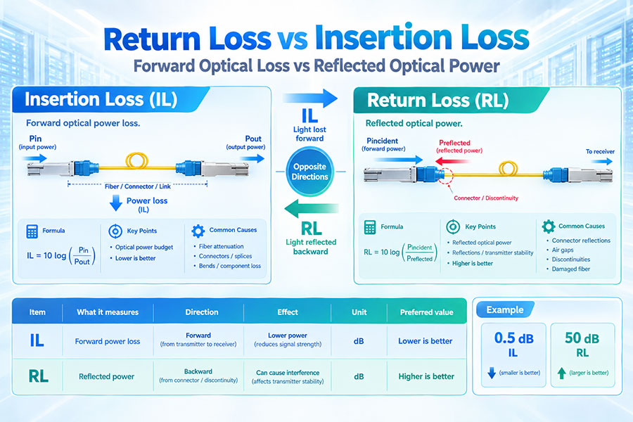
Insertion Loss measures how much optical power is lost while the signal passes through a fiber link or optical component. Return Loss measures how much optical power is reflected back toward the transmitter from discontinuities in the optical path. In simple terms, insertion loss describes how much light is lost forward, while return loss describes how much light comes back.
These parameters become increasingly important in high-speed optical networking because poor insertion loss reduces the available optical power budget, while excessive reflections can degrade transmitter and receiver performance. In advanced systems such as high-speed Ethernet, coherent optics, DWDM, PON, and dense fiber infrastructures, both parameters must be evaluated together.
Insertion Loss is the reduction in optical power that occurs when an optical component or transmission link is inserted into the signal path.
For a simple optical link:
Insertion Loss = 10 × log10(Pin / Pout)
where Pin is the optical power entering the device or link and Pout is the optical power measured at the output.
Insertion loss is normally expressed as a positive value in dB. Lower insertion loss generally means that more optical power reaches the receiver.
Return Loss measures the amount of optical power reflected back toward the source compared with the incident optical power.
The basic formula is:
Return Loss = 10 × log10(Pincident / Preflected)
Return Loss is expressed as a positive dB value. Unlike insertion loss, a higher return loss is better because it means less optical power is being reflected back toward the transmitter.
| Parameter | Insertion Loss | Return Loss |
|---|---|---|
| What it measures | Forward optical power loss | Reflected optical power |
| Basic effect | Reduces received optical power | Sends optical power back toward source |
| Formula | 10 log(Pin/Pout) | 10 log(Pincident/Preflected) |
| Unit | dB | dB |
| Preferred value | Lower | Higher |
| Typical causes | Fiber attenuation, connectors, splices, bends, component loss | Connector reflections, air gaps, discontinuities, damaged fiber |
| Primary concern | Optical power budget | Reflections and transmitter/receiver stability |
The terminology often causes confusion because both parameters contain the word "loss."
For insertion loss, a smaller number is desirable because less optical power is lost in the forward direction.
For return loss, a larger number is desirable because less optical power is reflected backward.
For example:
0.5 dB insertion loss is better than 1.0 dB.
50 dB return loss is better than 30 dB.
Reflectance describes the ratio of reflected optical power to incident optical power.
The formula is:
Reflectance = 10 × log10(Preflected / Pincident)
Reflectance is normally expressed as a negative dB value.
For the same event:
Return Loss = −Reflectance
For example, a reflectance of −50 dB corresponds to a return loss of +50 dB.
| Parameter | Return Loss | Reflectance |
|---|---|---|
| Physical meaning | Incident power compared with reflected power | Reflected power compared with incident power |
| Typical sign | Positive dB | Negative dB |
| Better performance | Higher value | More negative value |
| Example | 50 dB | -50 dB |
Optical Return Loss, or ORL, usually describes the total amount of optical power returned toward the source over an entire fiber link.
Unlike the reflectance of one connector or one event, total ORL can include contributions from multiple reflective events as well as distributed backscatter from the fiber.
This distinction is important when interpreting OTDR and optical return-loss measurements.
An individual connector, splice, break, or open fiber end can produce a localized reflection event.
An OTDR can locate these events and provide event reflectance information.
Total ORL considers the combined returned optical energy from the entire link.
Therefore:
Event Reflectance → Individual reflection event
ORL → Total returned optical power from the link
Insertion loss can be caused by several physical effects, including:
Fiber attenuation
Connector loss
Splice loss
Splitter or coupler loss
WDM component loss
Fiber bending
Misalignment
Contaminated connector end faces
The total insertion loss of a link is the combined effect of the relevant loss elements.
Return loss is primarily associated with reflections caused by discontinuities in the optical path.
Common causes include:
Air gaps between fiber end faces
Connector end-face defects
Fiber cracks
Open fiber ends
Connector misalignment
Contamination
Improper mating
Sharp or abnormal fiber conditions
When two fiber connectors are mated, their cores must be accurately aligned.
If the cores are laterally or angularly misaligned, only part of the optical field from the first fiber couples into the second fiber.
The uncoupled optical energy contributes to insertion loss.
A connector interface can also create a change in refractive index and optical-field conditions.
If the mating surfaces do not form a suitable optical interface, a portion of the incident light can be reflected toward the source.
Thus, one connector interface can affect both insertion loss and return loss, but through different physical mechanisms.
Dust, oil, residue, or other contamination on a fiber end face can prevent proper core alignment or create a physical gap.
This can increase insertion loss and reduce the amount of optical power reaching the receiver.
Connector inspection and cleaning are therefore important parts of fiber installation and maintenance.
Contamination can also create additional reflective interfaces or change the physical contact between connector surfaces.
This can increase back reflection and reduce return-loss performance.
For high-performance fiber systems, connector cleanliness is therefore relevant to both IL and RL.
Fiber attenuation is the loss occurring as optical power propagates through the fiber itself.
Insertion loss can include this fiber loss together with connector, splice, and component losses depending on how the measurement is defined.
Therefore, attenuation and insertion loss should not automatically be treated as identical terms.
Fiber bending can cause optical power to escape from the guided mode.
Macrobending, excessive bend radius, and certain forms of microbending can therefore increase optical loss.
In a high-speed network, unexpected bending can consume part of the available optical power budget.
Bending is primarily associated with increased attenuation, but severe physical damage or structural discontinuities can also contribute to reflection events.
However, bending and reflection should not be treated as the same physical mechanism.
A normal bend primarily causes additional forward loss, while a discontinuity such as a crack or open fiber end can create a strong localized reflection.
Fiber splices introduce optical insertion loss because the optical fields from the two fibers are not coupled with perfect efficiency.
Fusion splicing is generally designed to minimize this coupling loss, while mechanical splices can have different performance characteristics.
Splices can also generate reflection depending on the splice structure and refractive-index conditions.
WDM multiplexers and demultiplexers introduce insertion loss as optical signals pass through their optical filters and coupling structures.
In DWDM and CWDM systems, component insertion loss can be an important part of the optical link budget.
Keysight identifies insertion loss and return loss as important parameters for wavelength-dependent passive optical components such as multiplexers, demultiplexers, and filters.
Optical link budgets determine whether enough optical power reaches the receiver.
A simplified link-loss calculation is:
Total Link Loss = Fiber Loss + Connector Loss + Splice Loss + Passive Component Loss
The available optical margin is then evaluated against the transmitter and receiver specifications.
Excessive insertion loss can cause the received optical power to fall below the required receiver operating level.
Return loss is not normally added directly as a conventional dB attenuation term in a basic optical power budget.
Instead, it describes reflected optical energy that can affect signal quality and, depending on the system, the behavior of the transmitter and receiver.
Therefore, a link can have an acceptable insertion-loss budget but still have poor return-loss performance.
Yes.
Insertion loss and return loss measure different properties.
A connection can transmit most of the optical power forward while still producing a relatively large reflection from a discontinuity.
This is why high-performance optical systems can specify both parameters separately.
Yes.
For example, a fiber link can have low reflection but substantial attenuation due to long fiber length, multiple connectors, bends, or passive components.
Good return loss does not automatically mean low total insertion loss.
Although they are independent parameters, insertion loss and return loss can sometimes deteriorate together.
A damaged or contaminated connector can simultaneously increase forward loss and create additional reflections.
However, this is a correlation caused by the physical condition of the component, not a mathematical equivalence between IL and RL.
Connector geometry has a major influence on return-loss performance.
UPC connectors use a polished end face designed to make a physical optical contact between the two fiber surfaces.
APC connectors use an angled end face, commonly around 8 degrees, which directs much of the reflected optical energy away from the fiber core.
This makes APC particularly useful in applications that are sensitive to optical reflections.
| Characteristic | UPC | APC |
|---|---|---|
| End-face geometry | Ultra-polished | Angled polish |
| Typical reflection direction | More directly toward the source | Reflected light is directed away from the core |
| Return-loss performance | Good | Generally better |
| Common applications | General optical connectivity | PON, RF video and reflection-sensitive systems |
| Can APC and UPC be directly mated? | No | No |
Passive Optical Network systems can contain many passive connections and optical distribution components.
Reflections returning toward active optical transmitters can be undesirable in reflection-sensitive systems.
APC connectors reduce the amount of reflected optical energy directed back into the fiber core.
Return loss is particularly important in optical access networks because many optical components and connection points can exist between the OLT and ONU/ONT.
PON links may use APC connectors specifically to reduce reflections in the optical distribution network.
High-speed optical Ethernet systems can also be sensitive to optical reflections, particularly when transmitters use laser sources with characteristics affected by optical feedback.
As data rates increase, maintaining stable optical signal quality becomes increasingly important.
Return loss should therefore be considered alongside insertion loss, transmitter characteristics, receiver sensitivity, and the applicable PMD requirements.
Coherent optical systems use sophisticated transmitter and receiver architectures and can be sensitive to optical impairments, including unwanted reflections.
In coherent systems, the behavior of optical reflections can interact with laser characteristics, optical filtering, polarization, and other system parameters.
Therefore, return loss can become an important design and qualification parameter in coherent optical links.
DWDM systems contain many wavelength-sensitive optical components, including multiplexers, demultiplexers, filters, ROADMs, and other passive or active elements.
Reflections from these components can affect optical system performance.
Return loss can therefore be specified alongside insertion loss for wavelength-dependent optical components.
Reflected optical power can travel back toward the laser source.
Depending on the laser design, wavelength, optical isolation, and system architecture, optical feedback can affect transmitter behavior.
For reflection-sensitive systems, adequate return-loss performance helps limit unwanted optical feedback.
Insertion loss directly affects the optical power available at the receiver.
A simplified relationship is:
PRX = PTX − Total Optical Loss
when all quantities are represented consistently in dBm and dB.
As total insertion loss increases, the received optical power decreases.
Reflected optical signals can interact with transmitted or received signals and may create unwanted interference in some optical architectures.
The exact impact depends on the transmitter, receiver, wavelength, coherent properties, optical isolation, and network architecture.
Return loss should therefore be analyzed according to the applicable system rather than treated as a universal fixed penalty.
Insertion loss is commonly measured using an Optical Loss Test Set (OLTS), which combines a calibrated optical source with a power meter.
The test system measures the optical power before and after the link or component and calculates the resulting loss.
Insertion-loss testing is widely used for fiber cabling certification and component qualification.
Return loss can be measured using instruments designed to quantify reflected optical power.
OTDR-based measurements can identify reflective events and characterize their locations, while dedicated optical return-loss meters can measure return loss for a link or component.
Modern field instruments can support both optical power and insertion-loss measurements as well as optical return-loss measurements.
An OTDR sends optical pulses into the fiber and analyzes the light returning from Rayleigh backscatter and discrete reflection events.
This allows the tester to identify connectors, splices, bends, breaks, and other events along the fiber.
OTDR results can therefore provide much more information about the location of optical problems than a simple end-to-end insertion-loss measurement.
| Test Method | OLTS | OTDR |
|---|---|---|
| Primary use | End-to-end insertion loss | Event location and fiber characterization |
| Measures fiber length | Not the primary function | Yes |
| Locates connector events | No | Yes |
| Locates bends | Limited | Yes |
| Measures event reflectance | No | Yes |
| Measures total link loss | Yes | Yes, with different methodology |
Fiber insertion-loss measurements can be affected by launch conditions, connector reference methods, and direction-dependent characteristics of the test setup.
Testing in both directions can provide a more complete view of link performance and help identify abnormal connections or measurement inconsistencies.
Return loss is normally expressed in positive dB.
Examples include:
20 dB return loss
40 dB return loss
60 dB return loss
A higher value corresponds to a smaller reflected fraction of the incident optical power.
Reflectance is normally expressed as a negative dB value.
Examples include:
−20 dB
−40 dB
−60 dB
A more negative value represents less reflection.
A 30 dB return loss corresponds to:
Preflected / Pincident = 10−3
Therefore, approximately 0.1% of the incident optical power is reflected.
A 50 dB return loss corresponds to:
Preflected / Pincident = 10−5
Therefore, approximately 0.001% of the incident optical power is reflected.
This illustrates why a higher return-loss number represents better reflection performance.
An insertion loss of 1 dB means:
Pout / Pin = 10−0.1
Approximately 79.4% of the input optical power remains after the loss.
The remaining power is lost through attenuation, coupling inefficiency, scattering, reflection, or other mechanisms.
A 3 dB insertion loss corresponds to approximately half of the input optical power remaining at the output.
This is a much more significant power reduction than a typical low-loss fiber connector.
Fiber connectors are normally designed to have very low insertion loss.
Actual performance depends on connector type, manufacturing quality, alignment accuracy, contamination, mating condition, and fiber characteristics.
High connector loss consumes the available optical link budget.
Connector return loss is strongly influenced by end-face geometry, physical contact, core alignment, polishing quality, and contamination.
A good connector should transmit most of the incident power forward while minimizing reflection toward the source.
Patch cables contain connectors and fiber sections, so both insertion loss and return loss can contribute to overall link performance.
For high-density data center cabling, poor connector cleaning or repeated mating can gradually affect both parameters.
MPO/MTP connectivity introduces multiple fiber channels within a single connector.
Insertion loss must therefore be considered across all optical lanes.
Polarity, fiber alignment, end-face cleanliness, pin condition, and connector mating quality can affect the performance of the complete multi-fiber connection.
High-speed modules such as 400G DR4, 800G SR8, and other parallel optical architectures use multiple optical lanes.
Each lane can have its own loss characteristics.
System qualification therefore needs to consider lane-to-lane variation as well as total link loss.
Multiple optical lanes also create multiple opportunities for reflective events.
Connector quality and optical interface design must maintain acceptable reflection performance across all lanes.
As lane count and data rate increase, consistent connector and optical-engine quality becomes increasingly important.
WDM optical modules use multiplexers and demultiplexers to combine or separate wavelengths.
Each optical path introduces insertion loss.
Therefore, the optical budget must include not only fiber and connector losses but also WDM component losses.
WDM filters and coupling structures can also produce optical reflections.
Return-loss specifications can therefore be relevant to mux, demux, filters, splitters, and other passive optical components.
Wavelength-dependent measurements can be important because both insertion loss and return loss may vary with wavelength.
Insertion loss is not necessarily constant across the entire optical spectrum.
For wavelength-selective components, IL may vary with wavelength because of filter characteristics, coupling conditions, and device design.
This is particularly important for CWDM and DWDM equipment.
Return loss can also vary with wavelength.
A component that performs well at one wavelength may have different reflection characteristics at another wavelength.
Therefore, wavelength-swept measurements may be necessary for wavelength-dependent components.
| Component | Insertion Loss | Return Loss |
|---|---|---|
| Fiber connector | Important | Important |
| Patch cable | Important | Important |
| Fiber splice | Important | May be relevant |
| Splitter | Critical | Important |
| WDM Mux/Demux | Critical | Important |
| Optical filter | Critical | Important |
| Optical transceiver interface | Important | Important |
As Ethernet speeds increase, optical systems become more sensitive to available power and signal quality.
For short-reach modules, connector and fiber losses may consume a significant portion of the available optical budget.
For longer-reach modules, fiber attenuation and wavelength-dependent penalties become increasingly important.
High-speed optical transmitters can be affected by reflections from connectors, optical interfaces, and other discontinuities.
Return loss requirements should therefore be evaluated according to the transmitter technology and applicable optical interface specifications.
LPO reduces the amount of high-speed digital processing inside a pluggable optical module, but its optical link still requires a defined optical power budget.
Fiber loss, connector loss, WDM loss, and receiver sensitivity remain important.
Low insertion loss can therefore help preserve optical margin in LPO systems.
LPO relies on high-quality linear optical components and tight host-to-module signal integrity.
Although LPO is primarily an electrical architecture, optical reflections remain relevant to the transmitter and receiver performance of the optical engine.
Return loss should therefore be included in optical qualification where required by the applicable module specification.
Coherent systems often operate across longer distances and use high-performance optical components.
Total insertion loss can include fiber attenuation, connectors, WDM elements, filters, ROADMs, and other network components.
The optical design must ensure adequate received signal conditions for the coherent receiver.
Coherent transmitters and receivers can be sensitive to optical reflections depending on the laser, modulator, optical architecture, and system implementation.
Return-loss performance can therefore be an important qualification parameter in coherent optical networks.
When an optical link shows excessive insertion loss, a practical troubleshooting process should inspect:
Connector cleanliness
Connector mating
Fiber bends
Patch cable condition
Splice quality
Fiber continuity
WDM or passive component loss
Incorrect reference or test setup
OTDR testing can then help identify the location of individual loss events.
When return loss is too low, inspect:
Connector end faces
Air gaps
Connector damage
Fiber cracks
Open ends
Improper mating
Reflective passive components
OTDR event analysis can help locate strong reflection points.
Many field problems originate at fiber connector interfaces.
Contamination or poor mating can simultaneously increase insertion loss and reflection.
Therefore, connector inspection, cleaning, and proper mating are among the first checks when investigating unexpected optical performance.
An optical link with excessive insertion loss has reduced optical margin.
Temperature variation, aging, additional connectors, and component degradation can consume the remaining margin and eventually cause link instability.
A suitable optical design therefore requires adequate margin rather than simply meeting the nominal receiver sensitivity.
Persistent reflections can affect transmitter behavior or introduce unwanted optical interference depending on the system architecture.
For reflection-sensitive systems, maintaining appropriate return loss can therefore contribute to stable long-term operation.
| Design Question | Insertion Loss | Return Loss |
|---|---|---|
| How much optical power reaches the receiver? | Directly relevant | Indirectly relevant |
| How much power is reflected? | Not the primary metric | Directly relevant |
| Part of optical power budget? | Yes | Not as a simple attenuation term |
| Connector quality | Important | Important |
| Fiber length | Strong effect | Less direct |
| Reflection-sensitive laser | Secondary concern | Important |
| OTDR usefulness | Event analysis | Very important |
This is one of the most common terminology mistakes.
In optical communications, a return loss of 60 dB is better than 30 dB because the higher value means a smaller fraction of the incident optical power is reflected.
By contrast, insertion loss of 0.5 dB is better than 1.5 dB.
Return loss and reflectance describe the same reflection relationship using opposite sign conventions.
For the same event:
50 dB Return Loss = −50 dB Reflectance
The numerical signs should therefore be checked carefully when reading OTDR reports and component datasheets.
Return loss should not simply be added to fiber attenuation and connector insertion loss as though it were another forward attenuation term.
It is a measurement of reflected power, not a conventional forward transmission loss.
Low insertion loss is desirable, but it does not mathematically guarantee high return loss.
A component can have low forward loss while still exhibiting an undesirable reflective characteristic.
Both parameters should therefore be checked when the application requires them.
Fiber bending primarily causes additional attenuation.
A strong localized reflection is generally associated with a discontinuity or refractive-index change.
Severe physical damage can create both effects, but ordinary bending and reflection should not be treated as identical phenomena.
| Parameter | Insertion Loss | Return Loss |
|---|---|---|
| Measures | Forward loss | Backward reflection |
| Preferred value | Lower | Higher |
| Unit | dB | dB |
| Optical budget impact | Direct | Indirect |
| Typical causes | Attenuation, connectors, splices, bends, components | Discontinuities, gaps, connector reflections, cracks |
| Common test equipment | OLTS, optical power meter | OTDR, ORL meter |
| Good value example | 0.5 dB | 50 dB |
| Poorer value example | 2 dB | 20 dB |
A complete optical-link evaluation should include both forward-loss and reflection characteristics.
First, calculate or measure total insertion loss. Then compare the received optical power against the receiver requirements.
Next, evaluate return loss or ORL if the application is sensitive to reflections or the relevant specification requires it.
Finally, inspect individual events when abnormal results appear.
A typical acceptance process can include:
1. Fiber inspection
2. Connector cleaning
3. Insertion-loss measurement
4. Return-loss or ORL measurement when required
5. OTDR event analysis
6. Comparison against the applicable system limits
At 400G and 800G, optical links frequently use multi-fiber MPO/MTP connectivity or duplex single-mode fiber depending on the optical architecture.
Insertion loss becomes important because high-density links may have limited optical budgets.
Connector cleanliness, polarity, fiber alignment, and cable quality therefore have a direct impact on system reliability.
Optical transceiver qualification can include transmitter power, receiver sensitivity, insertion loss across external optical components, return loss, wavelength accuracy, extinction ratio, modulation quality, and other parameters.
The relevant limits depend on the PMD and module architecture.
As optical networks move toward 800G, 1.6T, and higher-capacity interfaces, optical signal margins become increasingly important.
Higher data rates do not change the basic definitions of IL and RL, but they increase the importance of controlling connector quality, optical interfaces, component losses, and reflection performance.
The simplest way to remember the difference is:
Insertion Loss asks: How much optical power is lost while the signal travels forward?
Return Loss asks: How much optical power is reflected back toward the source?
For insertion loss, lower is better.
For return loss, higher is better.
For reflectance, more negative is better.
Return Loss and Insertion Loss describe two different characteristics of an optical transmission system.
Insertion loss measures the reduction in forward optical power and is a key parameter in optical link budgets. Fiber attenuation, connectors, splices, bends, splitters, WDM components, and other passive elements all contribute to insertion loss.
Return loss measures the optical power reflected back toward the source. It is strongly influenced by connector interfaces, air gaps, surface defects, fiber discontinuities, and other reflective events.
For optical networking, the two parameters should be evaluated independently. A link can have low insertion loss but poor return loss, or good return loss but high insertion loss. High-quality optical connectivity therefore requires both low forward loss and adequate reflection performance.
For C-LIGHT optical transceivers, fiber cables, passive optical components, and high-speed 400G, 800G, and 1.6T optical systems, understanding the difference between IL, RL, and reflectance is important when designing optical budgets, qualifying components, troubleshooting links, and ensuring stable transmission performance.
For any questions, please contact us by email or WhatsApp.
Email: sales@c-light.com
WhatsApp: +86 132 6656 7067