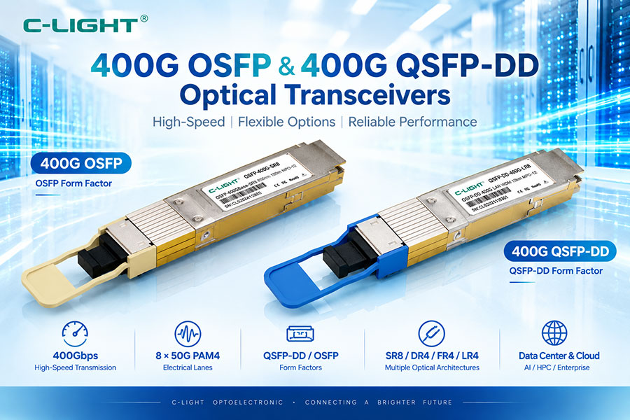
800G OSFP SR8 and 800G OSFP 2SR4 are short-reach optical transceivers designed for high-bandwidth AI, InfiniBand, HPC, and data center networks. Both C-LIGHT solutions use 8x100G PAM4 retimed 800GAUI-8 electrical interfaces, 850nm-class VCSEL optical engines, and support transmission up to 100m over OM4 multimode fiber. The key difference is the optical connector architecture: SR8 uses an MPO-16 interface, while 2SR4 uses two MPO-12 interfaces.
800G OSFP SR8 is an 800G short-reach optical transceiver using eight optical lanes. The referenced C-LIGHT CL800GOSFPSR8 supports 8x100G PAM4 retimed 800GAUI-8, 850nm-class VCSEL transmission, PIN receivers, and up to 100m over OM4 fiber.
800G OSFP 2SR4 is another 800G short-reach optical architecture. The referenced C-LIGHT CL800GOSFP2SR4-CLT also uses 8x100G PAM4 retimed 800GAUI-8 and eight VCSEL transmit channels with eight PIN receive channels. Its optical interface uses two MPO-12 APC connectors.
SR8 refers to an 8-lane short-reach architecture. The eight optical lanes collectively provide the 800G aggregate interface, with each lane operating at a 100G-class data rate.
2SR4 indicates a configuration that combines two SR4 groups. In the referenced C-LIGHT design, the eight optical lanes are presented through two MPO-12 APC connectors rather than a single MPO-16 interface.
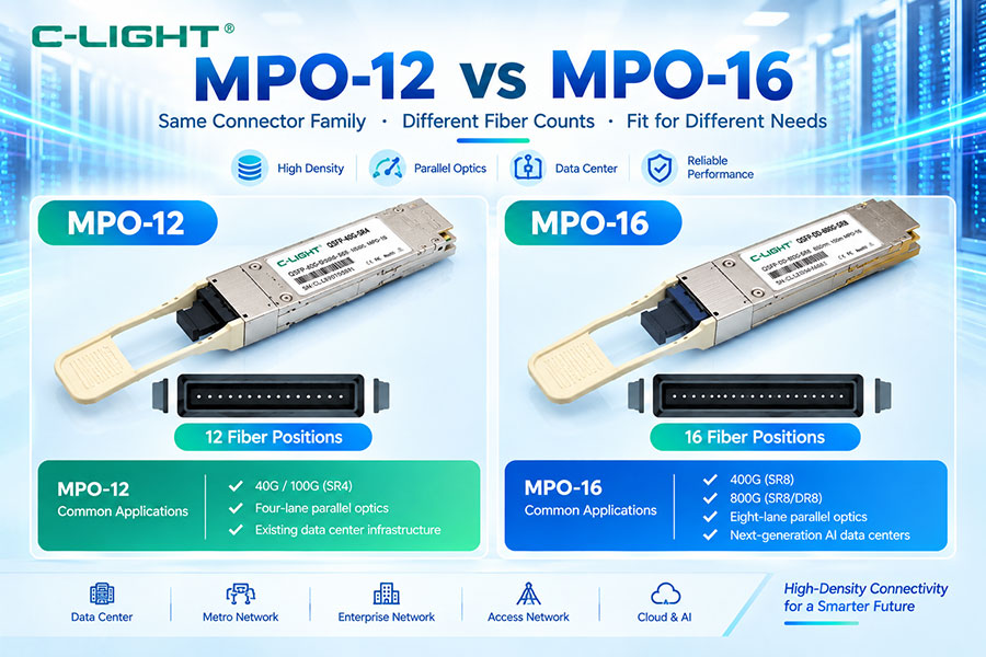
The most important difference is the optical connector structure. The C-LIGHT SR8 datasheet provides an MPO-16 APC interface and also references MPO-12 APC as an available connector option, while the 2SR4 Close Top version uses dual MPO-12 APC connectors. Their core 800G electrical and optical architecture is otherwise highly similar.
| Parameter | 800G OSFP SR8 | 800G OSFP 2SR4 |
|---|---|---|
| Form Factor | OSFP | OSFP |
| Aggregate Data Rate | 800G | 800G |
| Electrical Interface | 8x100G PAM4, retimed 800GAUI-8 | 8x100G PAM4, retimed 800GAUI-8 |
| Optical Technology | VCSEL + PIN | VCSEL + PIN |
| Optical Wavelength | 850nm class | 850nm class |
| Optical Lanes | 8 | 8 |
| Fiber | MMF | MMF |
| Maximum Reach | 60m OM3 / 100m OM4 | 60m OM3 / 100m OM4 |
| Optical Interface | MPO-16 / specified connector options | Dual MPO-12 APC |
| Operating Temperature | 0°C to 70°C | 0°C to 70°C |
| Maximum Power | <16W | <16W |
Both products use a retimed 800GAUI-8 electrical architecture. This means the host-side interface is based on eight high-speed electrical lanes, with each lane operating at a 100G-class signaling rate.
Both SR8 and 2SR4 use PAM4. Four signal levels are used to carry two bits per symbol, enabling the lane rates required for modern 400G and 800G systems. PAM4 also increases the importance of signal quality, equalization, FEC behavior, and optical performance.
The referenced C-LIGHT specifications list a per-lane data rate of 53.125 GBd with PAM4 modulation. Eight such optical lanes provide the 800G-class aggregate interface.
Both modules are specified as retimed optical interfaces. This architecture includes signal-conditioning and retiming functions within the transceiver, helping maintain the electrical and optical performance required by the 800GAUI-8 interface.
Both modules use VCSEL arrays for optical transmission. VCSEL technology is widely used for short-reach multimode fiber applications because it is well suited to high-density 850nm-class data center connectivity.
The receiver side of both C-LIGHT designs uses eight-channel PIN photodetector arrays. The eight receiver channels correspond to the eight optical lanes used by the 800G architecture.
The cited specifications identify an 850nm-class optical center wavelength. This aligns with short-reach multimode fiber deployments and the use of VCSEL technology.
Both modules are designed for multimode fiber. C-LIGHT specifies a maximum link length of 60m on OM3 and 100m on OM4. The actual link should remain within the fiber and transceiver specifications.
For the referenced products, OM3 supports up to 60m while OM4 supports up to 100m. OM4 is therefore the preferred fiber grade when the application requires the full 100m reach specified by the modules.
The SR8 datasheet identifies MPO-16 APC as the ordering interface and also states that MPO-12 APC and MPO-16 APC connectors are provided as supported options. This gives the SR8 family flexibility for different cabling implementations.
The 2SR4 Close Top module uses dual MPO-12 APC connectors. Instead of presenting all eight optical lanes through one MPO-16 interface, the architecture divides the optical connection across two MPO-12 interfaces.
MPO-16 provides a higher fiber count than MPO-12 and can be used to carry the eight transmit and receive optical lanes associated with an 800G SR8 architecture. The exact fiber assignment depends on the cable and polarity design.
Two MPO-12 connectors provide twelve-fiber interfaces on each connector. In an 800G 2SR4 architecture, the optical lanes are distributed across the two connectors, making the cabling structure different from a single MPO-16 SR8 link.
The connector difference changes how the optical lanes are physically mapped into the cable system. SR8 can consolidate the required optical channels into an MPO-16 interface, while 2SR4 uses two MPO-12 interfaces. Cable pinout and polarity must therefore match the selected module.
| Architecture | Typical Optical Interface | Cabling Structure |
|---|---|---|
| SR8 | MPO-16 | Single multi-fiber interface for the 8-lane architecture |
| 2SR4 | 2 × MPO-12 | Two multi-fiber interfaces carrying the 8 optical lanes |
MPO polarity is especially important with parallel optical links. The selected patch cable, trunk, cassette, and transceiver must use a compatible polarity scheme. This becomes more important in 2SR4 deployments because two separate MPO interfaces must be mapped correctly.
An SR8 transceiver should use a cable designed for the specified SR8 connector and lane mapping. A 2SR4 transceiver requires a dual-MPO-12 cabling arrangement. A cable should never be selected solely by the 800G label.
Both architectures can be integrated into breakout-oriented network designs where supported by the host system. The electrical lane mapping, optical lane grouping, connector type, and switch configuration must all match the intended breakout topology.
Both SR8 and 2SR4 are suitable for high-bandwidth AI data center networks where 800G short-reach optical connectivity is required. Typical links include switch-to-switch, switch-to-NIC, GPU cluster, and leaf-spine connections within supported distances.
The referenced C-LIGHT products support InfiniBand-oriented applications. The SR8 datasheet identifies an InfiniBand version, while the 2SR4 datasheet states support for both 8x100G Ethernet and InfiniBand NDR.
Both products can be used in 800G Ethernet environments when the host equipment supports the required OSFP and 800GAUI-8 interface. The specific cable and connector configuration must match the host platform.
AI clusters often require high-bandwidth links between GPU servers, network adapters, and switches. SR8 and 2SR4 can provide 800G optical connectivity for short-reach connections where multimode fiber is appropriate.
For short switch-to-switch links, either architecture can be used when the switch ports and cabling infrastructure are compatible. The connector structure is usually the primary practical consideration when deciding between SR8 and 2SR4.
Both solutions use the OSFP form factor, but the host-side mechanical interface alone does not determine complete compatibility. The switch must support the module's electrical interface, optical configuration, management functions, and supported cable architecture.
Both C-LIGHT datasheets specify CMIS 5.2 support. This provides a standardized management framework for supported host platforms, although the exact monitoring and control functions depend on implementation.
Both modules are designed as OSFP products and reference OSFP MSA compliance. The cited documentation states compliance with OSFP Module Specification Rev. 5.0.
The referenced C-LIGHT documentation lists IEEE 802.3db and IEEE 802.3ck compliance. These standards provide relevant electrical and optical requirements for modern high-speed Ethernet interfaces.
Both cited products specify power consumption below 16W across the 0°C to 70°C operating temperature range. This means power consumption is not the primary differentiator between the two referenced solutions.
Although both modules have similar specified maximum power, thermal conditions still matter in dense 800G switch systems. Airflow, OSFP cage design, adjacent port loading, and switch thermal limits should be considered during deployment.
The cited specifications list an average launch power range of approximately -1dBm to +4dBm per lane. Optical power should be evaluated together with receiver sensitivity and the total multimode fiber link budget.
Both C-LIGHT documents provide the same stated receiver sensitivity expression and stressed receiver sensitivity of approximately -2dBm. This further indicates that their core optical performance is closely aligned.
The two datasheets specify an optical return loss tolerance of 14dB. Proper connector cleanliness, polarity, and fiber quality remain important to maintaining the expected optical performance.
Both modules specify maximum TDECQ and TECQ values of 4.4dB per lane. These measurements are important for evaluating PAM4 transmitter quality and optical eye performance.
The maximum specified transmission distance is 60m over OM3 and 100m over OM4 for both referenced products. This makes them suitable for short-reach data center and AI cluster connectivity rather than long-distance DCI.
In practical deployment, the connector architecture is the biggest distinction. SR8 can use MPO-16-based cabling for the eight-lane optical link, while 2SR4 requires two MPO-12 connections. This affects patch-panel design, cable selection, fiber mapping, polarity management, and installation space.
SR8 can provide a more consolidated optical connection when an MPO-16 infrastructure is already available. 2SR4 may be more convenient when the network is designed around dual MPO-12 connections or an existing cabling architecture that uses MPO-12 components.
The overall cable-management requirements depend on connector count, cable routing, patch-panel structure, and rack density. A dual-MPO-12 implementation introduces two optical connector paths instead of one MPO-16 interface, which can affect physical cable organization.
Existing cabling should be checked before choosing between SR8 and 2SR4. If the installation is already based on MPO-16 trunks, an MPO-16 SR8 configuration can simplify the optical path. If the infrastructure is based on MPO-12 connections, 2SR4 may fit the existing cabling architecture more naturally.
Interoperability should be evaluated at the complete link level. Check host support, electrical lane mapping, optical connector type, cable polarity, fiber grade, management, FEC, and remote-end configuration before deployment.
For an SR8 link, check OSFP module recognition, MPO-16 polarity, fiber cleanliness, lane mapping, optical power, OM3 or OM4 fiber type, cable continuity, and remote-end configuration. FEC and host diagnostics can help identify lane-level errors.
For 2SR4, first verify that both MPO-12 interfaces are connected correctly and that the two optical groups are mapped according to the required lane configuration. Check polarity, connector cleanliness, fiber routing, optical power, and host configuration for both interfaces.
SR8 is suitable when the deployment is designed around an eight-lane 800G optical architecture and the host or cabling infrastructure supports MPO-16-based connectivity. It is particularly convenient where a consolidated multi-fiber interface is preferred.
2SR4 is suitable when the network platform and fiber infrastructure are designed around dual MPO-12 connectivity. Its two-connector architecture can integrate naturally with deployments that organize 800G connectivity as two SR4 groups.
| Selection Factor | SR8 | 2SR4 |
|---|---|---|
| Host Form Factor | OSFP | OSFP |
| Electrical Interface | 800GAUI-8 | 800GAUI-8 |
| Optical Lanes | 8 | 8 |
| Optical Technology | VCSEL + PIN | VCSEL + PIN |
| Wavelength | 850nm class | 850nm class |
| Fiber Type | MMF | MMF |
| OM3 Reach | 60m | 60m |
| OM4 Reach | 100m | 100m |
| Connector | MPO-16 or specified options | 2 × MPO-12 APC |
| Maximum Power | <16W | <16W |
| Operating Temperature | 0°C to 70°C | 0°C to 70°C |
From the referenced C-LIGHT specifications, the core optical and electrical performance of SR8 and 2SR4 is highly similar. The practical difference is mainly how the eight optical lanes are physically exposed and connected. Therefore, connector infrastructure and lane mapping should be treated as the primary selection criteria.
Common mistakes include choosing the cable only by the 800G data rate, mixing MPO-12 and MPO-16 cabling without verifying lane mapping, using incorrect polarity, connecting only one MPO-12 interface on a 2SR4 design, exceeding the OM3 or OM4 reach, or overlooking host compatibility.
For AI networks, both architectures provide the same basic 800G short-reach connectivity class described in the referenced documents. The decision should focus on switch port support, optical interface requirements, existing multimode fiber infrastructure, cabling topology, rack layout, and interoperability.
800G OSFP SR8 and 800G OSFP 2SR4 provide closely related short-reach 800G optical performance. Both use 8x100G PAM4 retimed 800GAUI-8 electrical interfaces, eight VCSEL transmit channels, eight PIN receive channels, 850nm-class optics, and multimode fiber with up to 60m reach on OM3 or 100m on OM4. The major difference is the optical interface: SR8 is associated with an MPO-16-based eight-lane connection, while the C-LIGHT 2SR4 Close Top design uses two MPO-12 APC connectors. For deployment, connector infrastructure, lane mapping, polarity, cabling topology, and host compatibility are more important than the 800G data-rate label itself.
For any questions, please contact us by email or WhatsApp.
Email: sales@c-light.com
WhatsApp: +86 132 6656 7067