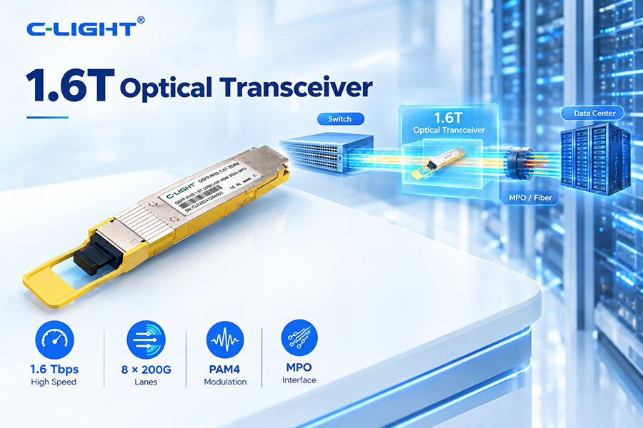
A 1.6T optical transceiver converts high-speed electrical data into optical signals for transmission over fiber and converts received optical signals back into electrical data. With an aggregate bandwidth of up to 1.6Tbps, these transceivers are designed for next-generation AI data centers, high-performance computing, and high-capacity Ethernet networks.
The operation of a 1.6T optical transceiver involves multiple stages, including electrical signal processing, optical modulation, fiber transmission, optical detection, electrical recovery, and module management.
A 1.6T optical transceiver is a high-speed optical module capable of supporting approximately 1.6Tbps of aggregate data transmission. It typically connects high-speed switches, routers, servers, or other network equipment through optical fiber.
The 1.6T data rate is achieved by combining multiple high-speed lanes. A common architecture uses eight 200G-class lanes, although the exact configuration depends on the transceiver and host platform.
The basic working process can be represented as:
Electrical Data → Signal Processing → Optical Conversion → Fiber → Optical Detection → Signal Processing → Electrical Data
On the transmit side, electrical signals from the host device are processed and converted into optical signals. On the receive side, incoming optical signals are detected and converted back into electrical signals for the host system.
A 1.6T optical transceiver can contain several major functional blocks:
High-speed electrical interface
DSP or signal-conditioning circuitry
Optical drivers
Laser or optical modulator
Photodetectors
Transimpedance amplifiers
FEC and signal-processing functions
Module management circuitry
Temperature and power monitoring
The exact component architecture varies according to the optical technology and module design.
One common way to achieve 1.6Tbps is to combine eight 200G-class lanes.
8 × 200G = 1.6Tbps
Each lane carries a portion of the aggregate data stream. Higher lane rates reduce the number of physical lanes required for a given bandwidth but increase the requirements for electrical and optical signal integrity.
The process begins when a switch ASIC, network processor, or other host device sends high-speed electrical signals to the optical transceiver.
At 1.6T, the electrical interface operates at extremely high lane rates. Package design, PCB routing, connectors, impedance control, and channel loss therefore become important factors in maintaining signal quality.
Many high-speed optical architectures use PAM4 signaling. PAM4 has four amplitude levels and carries two bits per symbol.
Compared with NRZ, PAM4 increases the amount of information transmitted per symbol, allowing higher data rates within a practical signaling bandwidth.
As lane rates increase, PAM4 helps achieve the required bandwidth without simply doubling the symbol rate for every bandwidth increase.
However, PAM4 has smaller eye openings and greater sensitivity to noise, loss, crosstalk, reflections, and other impairments. This makes signal conditioning and link-quality management especially important.
Depending on the module architecture, the incoming electrical signal may pass through DSP or other signal-conditioning circuitry before optical conversion.
Signal processing can perform functions such as equalization, clock recovery, FEC-related processing, and other high-speed signal-conditioning tasks.
A DSP can compensate for electrical and optical impairments and help maintain signal quality at high data rates. Its exact functions depend on the module architecture and networking standard.
DSP performance is closely related to module power consumption. As a result, improving DSP efficiency is an important part of 1.6T optical-module development.
The optical driver converts processed electrical signals into the appropriate drive signals for the optical transmitter.
Depending on the optical technology, the driver can control a laser or an external optical modulator. Driver bandwidth, linearity, power consumption, and signal quality directly affect optical transmission performance.
The transmitter generates an optical signal corresponding to the electrical data. Different 1.6T implementations can use different optical sources and modulation technologies.
Possible technologies include VCSEL-based solutions for short-reach applications, EML-based solutions for single-mode links, and silicon photonics or other integrated optical architectures.
The laser provides the optical carrier used to transmit data through fiber. Laser selection depends on wavelength, transmission distance, optical power, modulation method, temperature range, and system architecture.
Laser efficiency is an important factor in the total power consumption of a 1.6T optical transceiver.
The electrical data must be imposed on the optical carrier before transmission. This can be achieved through direct modulation or through an external modulator, depending on the optical architecture.
At high data rates, the optical transmitter must maintain sufficient bandwidth, extinction ratio, linearity, and eye quality.
The operating wavelength depends on the optical architecture. Short-reach multimode solutions can use approximately 850nm-class wavelengths, while single-mode solutions can use 1310nm-class or other wavelength bands.
WDM architectures can combine multiple wavelengths to provide higher aggregate bandwidth over a fiber pair.
After optical conversion, the signal travels through an optical fiber. The fiber carries the modulated light from the transmitting transceiver to the receiving transceiver.
Transmission performance depends on fiber attenuation, connector loss, dispersion, reflections, optical power, and the overall link budget.
Multimode fiber can be used for some short-reach optical architectures. It is particularly relevant to high-density connections within data centers where transmission distances are relatively short.
OM3, OM4, and OM5 are common multimode fiber categories used in high-speed data-center infrastructure.
Single-mode fiber supports longer transmission distances and is widely used for data-center and data-center-interconnect applications.
Single-mode 1.6T transceivers can use multiple optical channels or WDM architectures to achieve the required aggregate bandwidth.
At the receiving end, photodetectors convert incoming optical signals into electrical signals.
The receiver must detect small variations in optical power while maintaining sufficient sensitivity and signal quality at the required data rate.
Photodetectors convert optical energy into electrical current. The detector technology depends on the wavelength, data rate, optical architecture, and receiver design.
Receiver performance affects sensitivity, BER, dynamic range, and overall link margin.
A transimpedance amplifier, or TIA, converts the current generated by the photodetector into a usable voltage signal.
The TIA must provide adequate bandwidth, gain, noise performance, and linearity for high-speed receiver operation.
The recovered electrical signal may then pass through signal-processing and equalization functions before being delivered to the host device.
Depending on the architecture, the receiver path can include DSP, equalization, clock recovery, FEC processing, or other functions.
Forward Error Correction helps compensate for transmission errors within the limits defined by the applicable networking standard.
At high-speed PAM4 data rates, FEC can play an important role in achieving the required error performance. The specific FEC implementation depends on the host system and standard.
Bit Error Rate is a key measurement of high-speed optical-link quality. It represents the proportion of transmitted bits that are received incorrectly.
A 1.6T optical link must maintain suitable BER performance across the complete electrical and optical path, including the host interface, transceiver, fiber, connectors, and remote endpoint.
The optical link budget determines whether sufficient optical power is available at the receiver after accounting for transmission losses.
Important factors include transmitter output power, fiber attenuation, connector loss, splice loss, passive-component loss, receiver sensitivity, and design margin.
Receiver sensitivity represents the minimum received optical power required to achieve a specified performance level.
High-speed PAM4 systems require careful control of receiver sensitivity because reduced signal margins can affect BER and overall link reliability.
The connector depends on the optical architecture. Parallel optical designs can use multi-fiber MPO/MTP connectors, while wavelength-multiplexed designs can use duplex LC or other connector configurations.
Connector type, fiber count, polarity, insertion loss, and cleanliness all affect link performance.
Power consumption is a major consideration in 1.6T optical-transceiver design. Major contributors can include DSPs, optical drivers, lasers, modulators, TIAs, receivers, management circuits, and thermal-management components.
Higher module power increases thermal density and can affect the total power budget of high-density network switches.
Power per bit provides a useful way to evaluate energy efficiency.
Rather than comparing only absolute module power, designers can evaluate how much power is required to transmit a given amount of data. This becomes particularly important when comparing 400G, 800G, and 1.6T technologies.
Heat generated by the electrical and optical components must be removed to maintain reliable operation.
Thermal design can include heatsinks, optimized airflow, thermal interface materials, chassis-level cooling, and in some high-density systems, liquid cooling.
At 200G-class lane rates, electrical-channel impairments become increasingly significant. PCB traces, packages, connectors, and other interconnect structures can introduce insertion loss, reflections, crosstalk, and inter-symbol interference.
The complete electrical channel must therefore be designed and validated as part of the 1.6T system.
Linear-drive pluggable optics, or LPO, reduces or bypasses certain signal-processing functions inside the optical module. More signal-processing responsibility is placed on the host ASIC and electrical channel.
LPO can potentially reduce module power and latency, but it requires strong host SerDes performance and careful electrical-channel design.
Co-Packaged Optics places optical engines much closer to the switching ASIC. The shorter electrical path can reduce channel loss and improve the ability to manage high-speed electrical signals.
CPO and 1.6T describe different aspects of the system: 1.6T refers to bandwidth, while CPO refers to the physical integration architecture.
Silicon photonics integrates multiple optical functions into a photonic integrated circuit. Depending on the design, these functions can include waveguides, modulators, wavelength multiplexers, splitters, and photodetectors.
Silicon photonics is being considered for high-bandwidth optical interconnects because of its integration and scalability potential.
AI data centers generate large amounts of east-west traffic between GPUs, servers, network adapters, switches, and storage systems.
1.6T optical transceivers can provide higher-capacity connections for next-generation AI fabrics, particularly as switch bandwidth and GPU-cluster scale increase.
GPU servers require high-speed network connections to switches. Depending on distance and architecture, these links can use DAC, AEC, AOC, or optical transceivers.
Optical connectivity becomes increasingly useful as bandwidth and transmission distance increase.
High-capacity switches require large numbers of inter-switch connections. 1.6T optical interfaces can increase bandwidth per port and support higher aggregate network capacity.
This can be important in leaf-spine and other scalable network architectures.
Higher bandwidth per port can reduce the number of ports required to achieve a specific aggregate capacity. However, higher-speed ports also increase power and thermal density.
1.6T optical transceiver design therefore requires simultaneous optimization of bandwidth, power, cooling, packaging, and optical performance.
High-speed optical transceivers include management and monitoring functions that can provide information about temperature, voltage, optical power, laser bias, alarms, and other operating parameters.
These functions help network operators monitor module health and troubleshoot optical-link problems.
Testing should cover the complete electrical and optical performance of the module.
Optical output power
Receiver sensitivity
Wavelength accuracy
Extinction ratio
Eye quality
BER performance
FEC performance
Electrical signal integrity
Power consumption
Temperature performance
Host interoperability
If a 1.6T optical link fails to establish, engineers should check the complete path from the host ASIC to the remote endpoint.
Module recognition
Host compatibility
EEPROM or coding
Electrical lane configuration
FEC settings
Fiber type
Connector polarity
Optical power
Receiver sensitivity
Temperature
Remote-end configuration
| Characteristic | 800G | 1.6T |
|---|---|---|
| Aggregate Bandwidth | 800Gbps | 1.6Tbps |
| Common Lane Concept | 100G-class | 200G-class |
| Signal Integrity | High Requirement | Higher Requirement |
| Power and Thermal Density | High | Higher |
| Target Applications | AI and Data Centers | Next-Generation AI and High-Capacity Networks |
A 1.6T optical transceiver works by converting high-speed electrical signals into optical signals and transmitting them through fiber, then detecting and recovering the optical signals at the receiving end.
A typical implementation can combine eight 200G-class lanes and use technologies such as PAM4, high-speed drivers, optical sources, photodetectors, TIAs, DSP or other signal-conditioning functions, and FEC. The complete system must also address optical link budget, signal integrity, power consumption, thermal management, and interoperability.
As AI data centers move toward higher network bandwidth, 1.6T optical transceivers provide a path toward higher-capacity switch and interconnect architectures. Technologies such as LPO, CPO, and silicon photonics can further influence how future 1.6T optical systems are designed and deployed.
For any questions, please contact us by email or WhatsApp.
Email: sales@c-light.com
WhatsApp: +86 132 6656 7067