An optical DSP, or Digital Signal Processor, processes high-speed electrical signals in an optical transceiver to improve signal quality and enable reliable optical transmission. It performs functions such as equalization, clock and data recovery, signal correction, and monitoring. Optical DSPs are widely used in high-speed PAM4 systems such as 400G, 800G, and emerging 1.6T optical networks.
An optical DSP is a digital signal processing chip used in high-speed optical communication equipment. In a conventional DSP-based optical transceiver, it sits between the host electrical interface and the optical components.
Its main purpose is to process distorted or degraded high-speed signals so that they can be transmitted and received reliably.
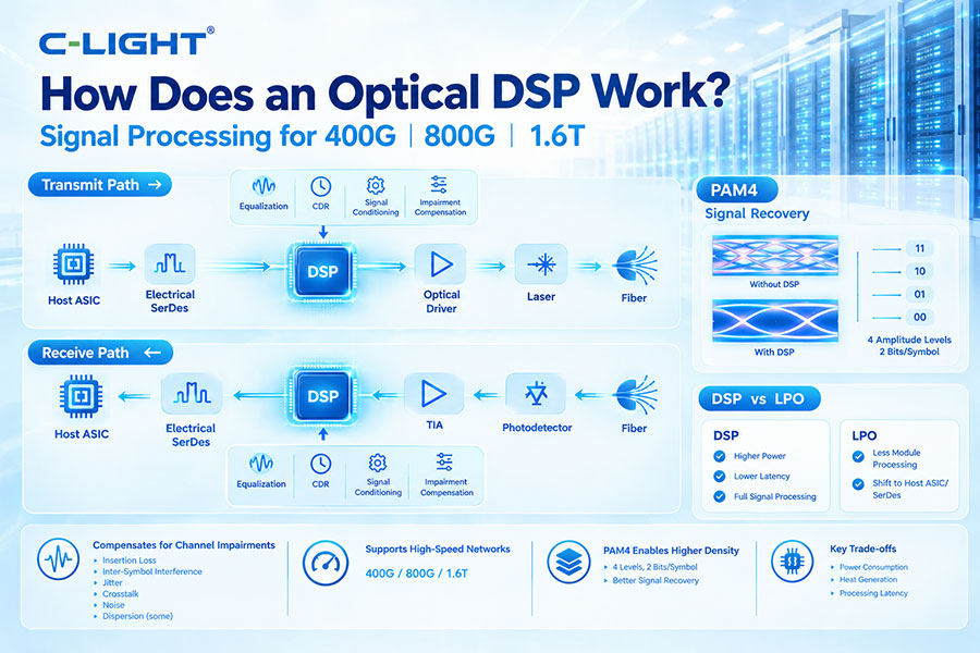
A simplified transmit path is:
Host ASIC → Electrical SerDes → DSP → Optical Driver → Laser → Fiber
A simplified receive path is:
Fiber → Photodetector → TIA → DSP → Electrical SerDes → Host ASIC
The DSP receives a high-speed electrical signal, digitally processes it, compensates for channel impairments, and sends the conditioned signal to the next stage.
At high data rates, electrical and optical signals are affected by insertion loss, inter-symbol interference, jitter, crosstalk, noise, and other impairments.
These effects can make it difficult for the receiver to correctly identify signal levels. The DSP helps recover and reshape the signal so the system can meet its required performance.
An optical DSP can perform several signal-processing functions, including:
Transmit equalization
Receive equalization
Clock and data recovery
Signal conditioning
Digital filtering
Signal impairment compensation
Monitoring and diagnostics
FEC processing in supported architectures
On the transmit side, the DSP receives data from the host SerDes and processes the electrical waveform before it reaches the optical driver.
It can apply digital equalization and other signal-conditioning functions to compensate for losses and distortion in the electrical path between the host ASIC and optical transmitter.
On the receive side, the photodetector and TIA generate an electrical signal from the received optical signal.
The DSP analyzes and processes this signal to compensate for distortion, recover timing information, reduce inter-symbol interference, and reconstruct the transmitted data.
Equalization is one of the most important DSP functions. High-speed electrical channels do not transmit all frequency components equally. Higher-frequency components may experience greater attenuation, causing signal distortion.
The DSP applies digital filtering and equalization algorithms to compensate for this frequency-dependent loss.
Transmit equalization compensates for signal degradation before the electrical signal reaches the optical transmitter.
The DSP can adjust the waveform so that the signal arriving at the driver and optical device remains within the required operating range.
Receive equalization compensates for distortion present in the received electrical signal after optical detection.
The DSP uses digital processing to improve the signal eye opening and reduce the effects of inter-symbol interference and channel loss.
Clock and Data Recovery, or CDR, extracts timing information from the incoming signal and uses it to correctly sample the transmitted data.
CDR can be implemented as part of or alongside the DSP architecture depending on the specific transceiver design.
PAM4 uses four amplitude levels to transmit two bits per symbol. Because the distance between adjacent levels is smaller than in a two-level NRZ signal, PAM4 is more sensitive to noise and distortion.
The DSP helps compensate for these impairments and enables the receiver to distinguish the four signal levels accurately.
Modern high-speed optical interfaces such as 400G and 800G commonly use PAM4 signaling. At these speeds, the electrical channel becomes more difficult to manage.
PAM4 DSP provides the equalization and signal-recovery capabilities needed to maintain reliable communication across these channels.
A PAM4 signal contains three eye openings. Noise, jitter, loss, and inter-symbol interference can reduce these eye openings and cause symbol errors.
The DSP uses equalization and filtering to compensate for signal degradation and improve the quality of the received waveform.
FEC and DSP have different roles. DSP processes the physical signal, while FEC adds redundancy that allows the receiver to detect and correct certain errors.
In some architectures, FEC-related processing may be integrated with the DSP, while in other systems it is handled by the host ASIC or another device.
DSP can compensate for certain signal distortions caused by the transmission channel, but it does not physically restore optical power lost in the fiber.
Optical loss is primarily managed through transmitter output power, receiver sensitivity, optical amplifiers where applicable, and optical link-budget design.
Chromatic dispersion causes different spectral components of a signal to propagate at different velocities through fiber. In suitable optical systems, DSP can digitally compensate for dispersion-induced signal distortion.
The amount of compensation depends on the DSP architecture, modulation format, wavelength, transmission distance, and optical system.
No. DSP has finite processing capability. It can compensate for many predictable electrical and optical impairments, but excessive noise, insufficient optical power, severe nonlinear effects, or other conditions may exceed its correction capability.
Good optical and electrical engineering is therefore still essential.
A 400G optical transceiver may use multiple PAM4 lanes to achieve an aggregate 400Gbps data rate.
The DSP processes these lanes, providing transmit and receive equalization, timing recovery, and other signal-processing functions required for reliable high-speed operation.
800G optical transceivers commonly use 8 × 100G-class PAM4 lanes. The DSP processes multiple high-speed lanes simultaneously while maintaining signal integrity and low error performance.
Because the aggregate processing bandwidth is much higher than in earlier generations, 800G DSPs require high processing efficiency and careful thermal design.
1.6T-class optical interfaces can use 200G-class electrical lanes. At these speeds, the electrical channel becomes even more difficult to manage.
The DSP must provide very high processing bandwidth while meeting strict requirements for power consumption, latency, signal integrity, and thermal performance.
The term optical DSP is commonly used for DSPs designed for optical communication systems. The DSP itself performs electrical digital processing, even though it is part of an optical transceiver.
Its purpose is to manage signals associated with the optical communication path rather than directly processing the optical waveform as an analog optical component would.
| Component | Main Function |
|---|---|
| DSP | Digital signal processing, equalization, and signal recovery |
| TIA | Converts photodiode current into a high-speed electrical signal |
The optical driver converts the electrical signal into a suitable drive waveform for the optical transmitter. The DSP processes the data and electrical signal before it reaches the driver.
The two components therefore perform complementary functions.
DSP processing consumes electrical power. As data rates increase, more processing capability is required, which can increase the power consumption and heat generated inside the optical module.
This has become a major design consideration for high-speed 800G and 1.6T optical transceivers.
Power consumed by the DSP is converted into heat. The resulting thermal load must be removed through the optical module and system cooling architecture.
Efficient DSP design, packaging, heatsinks, and system airflow or liquid cooling can all contribute to thermal management.
Yes. DSP processing introduces some latency because the signal must pass through digital processing stages.
Modern optical DSPs are designed to minimize this delay, but the exact latency depends on the DSP architecture and implementation.
| Feature | DSP-Based Optics | LPO |
|---|---|---|
| Module DSP | Included | Traditional DSP removed |
| Module power | Higher | Lower potential |
| Signal processing | Strong module-side processing | More host-side processing |
| Channel tolerance | Generally higher | More demanding |
| Host dependency | Lower | Higher |
LPO removes the traditional DSP from the optical module primarily to reduce module power and processing overhead.
More signal-conditioning responsibility is shifted to the host ASIC and its SerDes interface. This can simplify the optical module but places greater requirements on the host electrical channel.
DSP can improve tolerance to certain signal impairments and may help a system achieve its specified transmission performance, but it does not independently define optical reach.
Transmission distance depends on factors including optical power budget, fiber loss, transmitter characteristics, receiver sensitivity, dispersion, modulation format, and the applicable optical standard.
DSP-based optical modules can be evaluated using electrical and optical performance measurements such as:
BER
Pre-FEC and post-FEC performance
Eye diagram
TDECQ
Jitter
Receiver sensitivity
Optical modulation amplitude
Power consumption
Processing latency
The main advantages include:
Strong signal equalization
Improved PAM4 signal recovery
Compensation for electrical-channel impairments
Support for high-speed optical interfaces
Improved system interoperability in many architectures
Support for demanding optical transmission conditions
The main limitations are higher power consumption, additional heat, processing latency, and increased optical module complexity.
These limitations become increasingly important as optical interfaces move toward higher bandwidths.
AI data centers require large numbers of high-speed connections between GPUs, switches, servers, and other systems. PAM4-based 400G and 800G links must maintain reliable operation despite increasingly demanding electrical channels.
Optical DSPs provide the signal-processing capability needed to manage these conditions while supporting high aggregate bandwidth.
Optical DSP technology is evolving toward higher processing speeds, lower power consumption, lower latency, and more advanced equalization algorithms.
At the same time, architectures such as LPO and CPO are being developed to reduce electrical interconnect loss and power consumption. DSP-based optics will remain important where strong signal processing and deployment flexibility are required.
An optical DSP works by digitally processing high-speed electrical signals before optical transmission and after optical reception. Through equalization, clock recovery, signal conditioning, and other processing functions, it compensates for signal impairments and helps maintain reliable PAM4 communication. Optical DSPs are a key technology for 400G, 800G, and 1.6T optical networks, although their power and thermal requirements are driving interest in alternative architectures such as LPO and CPO.
For any questions, please contact us by email or WhatsApp.
Email: sales@c-light.com
WhatsApp: +86 132 6656 7067