Uneven optical link performance can introduce communication delays, create GPU stragglers, and reduce the efficiency of synchronized training across large AI clusters.
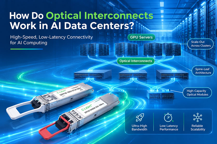
Distributed AI training divides computational work across multiple GPUs or accelerator nodes. Each device processes a portion of the workload and exchanges data with other participants through high-speed networks. Optical interconnects provide much of the bandwidth required to connect servers, switches, and distributed computing resources.
However, a high nominal link speed does not guarantee uniform network performance. One optical connection may experience reduced bandwidth, increased errors, intermittent signal degradation, or heavier congestion than other paths. This condition can create optical link imbalance: a difference in effective transmission capacity, reliability, latency, or traffic utilization across connections that participate in the same workload.
In synchronous training, the consequences can extend beyond the affected link. If one worker completes a communication operation more slowly than its peers, other workers may have to wait for the collective operation to finish. The resulting delay can reduce accelerator utilization and lengthen the time required to complete each training step.
1. What Is Optical Link Imbalance?
Optical link imbalance occurs when connections intended to serve a coordinated workload do not deliver equivalent effective performance. The difference may arise from unequal link capacity, different network paths, varying queue utilization, impaired optical signal quality, or intermittent link degradation.
Not every optical connection in a data center needs identical performance. Different links may intentionally serve different distances, traffic volumes, or network roles. Imbalance becomes a concern when a slower or less reliable path constrains a workload that depends on coordinated communication across multiple links or participants.
Bandwidth Imbalance
One link may have lower effective throughput than others because of a reduced negotiated speed, a degraded interface, an impaired cable or transceiver, or insufficient capacity on the selected route. Traffic assigned to that connection can take longer to complete even when other links remain underutilized.
Latency Imbalance
Different paths can have different end-to-end latency because of route length, queueing, switching behavior, traffic contention, or retransmission and recovery events. In synchronized communication, even a relatively small persistent delay can affect the time at which a worker reaches a collective operation's completion point.
Signal-Quality Imbalance
Optical links can differ in received optical power, available link margin, error rates, and physical-layer health. A link operating close to its specified limits may exhibit more error-related events or become unstable under changing environmental or traffic conditions.
Correctable FEC errors or a lower received optical power do not automatically mean that a link has lower throughput. They are diagnostic indicators whose significance depends on the transceiver specification, error statistics, and whether the link is experiencing consequential faults, retraining, or loss of connectivity.
Core principle: Link imbalance matters when differences between communication paths affect the completion time of the overall workload. Optical power, bandwidth, latency, error rate, and traffic utilization must be evaluated together rather than treating any single metric as a complete diagnosis.
2. Why Distributed Training Is Sensitive to Uneven Links
Distributed training uses communication operations to combine information calculated by different workers. In data-parallel training, GPUs commonly exchange and aggregate gradients so that model replicas can apply coordinated updates.
Collective communication algorithms such as AllReduce, Reduce-Scatter, and All-Gather move data among participating devices. Their performance depends on the algorithm, message size, network topology, available bandwidth, and the behavior of the participating workers.
Many synchronous workloads have a critical-path dependency: a step cannot fully complete until its required communication operations finish. A worker with a slow link, congested route, or degraded network interface may therefore delay the collective even if most of the cluster operates normally.
The Straggler Effect
A straggler is a worker that progresses more slowly than its peers. Slow computation, data loading, memory pressure, or network performance can all create this condition. An optical link problem is one possible cause, but it should not be assumed to be the explanation for every slow training rank.
When a worker experiences reduced network bandwidth, it may take longer to send or receive collective data. Other workers can finish their own contributions and then wait for the collective to complete, reducing the amount of useful work performed during that interval.
Communication Becomes the Limiting Resource
Increasing GPU performance does not necessarily shorten a training step when communication remains the limiting factor. If the network cannot deliver data at the rate required by the workload, additional computing capacity may contribute less improvement than expected.
Optical link imbalance can worsen this problem because the cluster's effective communication performance may be determined by the most constrained path or participant rather than the average bandwidth of all links.
3. How Optical Link Imbalance Reduces Training Efficiency
This sequence is most relevant to workloads with synchronization dependencies. Asynchronous workloads, adaptive collective algorithms, and communication schedules that overlap data transfer with computation can respond differently, although they can still suffer from lower aggregate communication capacity.
4. How Unequal Link Performance Affects Collective Communication
AllReduce Synchronization
AllReduce combines values from multiple workers and makes the reduced result available to participating devices. In synchronous data-parallel training, this operation is frequently used to aggregate gradients.
In a ring-based AllReduce, participants exchange data through a sequence of communication steps. If one participant or one of its required links has substantially lower effective bandwidth, the affected communication stages can take longer. Other participants may then wait for the slowest required stage to finish.
Tree-based and other collective algorithms have different communication patterns, so their sensitivity to an individual link or worker can differ. There is no single slowdown factor that applies to every algorithm or topology.
Reduce-Scatter and All-Gather
Reduce-Scatter distributes and reduces portions of the data across participants, while All-Gather collects distributed portions so they become available more broadly. These operations can be used independently or as components of larger collective algorithms.
A bottlenecked connection can delay the transfer of particular data partitions or slow a communication stage. Depending on the topology and algorithm, the impact may remain localized or affect a larger portion of the collective.
Communication and Computation Overlap
Training frameworks may overlap communication with the remaining computation to reduce exposed network time. If communication completes within the available overlap window, a link-performance difference may have little effect on the training step.
When the communication delay exceeds that window, the remaining transfer becomes visible on the critical path. This can cause GPU idle periods or longer synchronization phases even if average network utilization appears acceptable.
5. Common Causes of Optical Link Imbalance
| Cause | Network Effect | Potential Training Impact |
|---|---|---|
| Unequal interface capacity | Some links have lower negotiated speed or less available bandwidth. | Traffic on constrained paths takes longer to complete. |
| Uneven ECMP or LAG utilization | Hashing, topology, or traffic distribution sends disproportionate load over certain links. | Queues build on heavily loaded paths while other connections remain underused. |
| Optical power margin problems | A link operates close to specified transmit or receive limits. | May indicate reduced robustness or contribute to link faults if the limits are violated. |
| Elevated physical-layer errors | Corrected errors increase or uncorrectable errors and link recovery events occur. | Depending on severity and implementation, errors can contribute to instability, recovery overhead, or traffic loss. |
| Intermittent link flapping | The link repeatedly changes state and triggers failover or route recalculation. | Bandwidth can temporarily fall and traffic may be redistributed repeatedly. |
| Unequal route latency | Different paths exhibit different queueing delays or transmission distances. | Some communication stages complete later, potentially delaying synchronization. |
| Traffic contention | Storage, training, and other traffic compete for shared links or switch resources. | Latency and completion times vary with the workload and competing traffic. |
Several causes can coexist. For example, a degraded optical connection may cause route failover, which concentrates traffic on fewer remaining links. The resulting congestion can then increase communication time even after the routing system has restored connectivity.
6. Optical Signal Quality and Network Performance
Optical link health is an important part of diagnosing potential imbalance, but optical diagnostics must be interpreted in the context of the selected module and system.
Transmit and Receive Optical Power
Digital Diagnostic Monitoring (DDM) or Digital Optical Monitoring (DOM), where supported, can provide transmit and receive optical power measurements along with other operating parameters. Comparing these readings with the module's specification can help identify a weak optical path, a receiver operating near its sensitivity limit, or unexpected changes over time.
Optical power is not a direct measurement of application throughput. A link with sufficient optical power can still suffer from congestion, an interface configuration mismatch, or other performance limitations. Conversely, a low reading is significant only in relation to the specified operating range and the actual link budget.
FEC and Error Statistics
Forward Error Correction helps receivers correct eligible transmission errors. Corrected-error counters can provide useful information about the physical link margin and signal quality. A rising error rate may indicate that a link deserves investigation before it begins experiencing more serious faults.
However, corrected FEC errors do not necessarily translate directly into lower Ethernet throughput. Engineers should distinguish corrected errors from uncorrectable errors, packet drops, retraining, and interface resets before concluding that FEC activity is causing a training slowdown.
Link Stability and Temperature
Intermittent loss of signal, interface resets, or repeated link retraining can interrupt traffic and trigger routing changes. Module temperature and other diagnostic readings can help determine whether an environmental or equipment issue coincides with the degradation.
The investigation should include the transceiver, host port, cable assembly, connectors, fiber path, and the equipment at the other end. Replacing an optical module without checking the full path may leave the actual source of imbalance unresolved.
7. Why Nominally Identical Optical Links May Perform Differently
Two links can use the same nominal data rate and transceiver type but still exhibit different behavior under load. They may have different route lengths, connector losses, queue utilization, traffic patterns, host configurations, or upstream network conditions.
Optical module specifications define supported operating conditions, not guaranteed equality of end-to-end application performance. The performance of a training link depends on the complete path from the source NIC through switches and fiber to the destination NIC.
Similarly, unequal receive power does not necessarily mean that one link carries less traffic or has higher latency. A meaningful comparison requires optical readings, physical-layer error counters, link utilization, queue telemetry, and application-level measurements.
| Measurement | What It Reveals | What It Cannot Establish Alone |
|---|---|---|
| Optical transmit and receive power | Whether optical levels fall within the module's specified operating range. | Whether the link is congested or slowing collective communication. |
| FEC and physical error counters | Evidence of signal-quality issues or changes in error behavior. | Whether errors are the primary cause of the observed training slowdown. |
| Interface throughput and utilization | How much capacity the connection is using. | Whether the load reflects useful payload, contention, or an unrelated system bottleneck. |
| Queue depth and congestion telemetry | Where traffic is accumulating and whether congestion is present. | Whether the original cause is a physical fault, traffic imbalance, or insufficient capacity. |
| Per-rank training and collective timings | Which workers are delayed and whether collective communication is on the critical path. | Whether an optical link is responsible without supporting network evidence. |
8. How to Diagnose and Reduce Optical Link Imbalance
The most effective approach combines physical-layer verification with network telemetry and distributed-training profiling. The aim is to establish whether a link is actually limiting the workload, identify the source of the imbalance, and validate that a change improves end-to-end performance.
Establish a baseline: Record the expected speed, topology, route, utilization, and normal latency of the affected links.
Compare optical diagnostics: Check transmit and receive power, temperature, voltage, laser bias, and available module alarms against the relevant specifications.
Inspect physical error counters: Compare corrected and uncorrectable FEC errors, CRC/FCS errors, link retraining, and loss-of-signal events where the equipment exposes them.
Evaluate traffic distribution: Compare ECMP or LAG path utilization, per-port throughput, queue occupancy, drops, and congestion indicators.
Profile distributed training: Measure per-rank step times, communication durations, collective completion times, and the amount of communication hidden by computation.
Check host and path consistency: Verify link speed, interface configuration, transceiver compatibility, routing, and relevant NIC settings.
Test one change at a time: Where appropriate, substitute a known-good cable or module, move traffic to a verified route, or correct the identified configuration issue.
Repeat tests under representative load: Compare error rates, traffic distribution, collective timing, training step time, and accelerator utilization after the change.
Do not conclude that a module is defective merely because its optical power differs from another module. The correct reference is the product specification and actual performance of the complete link. Likewise, changing routing or load-balancing settings may hide symptoms without resolving a weak physical connection.
9. Optical Transceiver Options for High-Bandwidth AI Fabrics
Optical transceiver selection affects the available bandwidth, supported transmission distance, fiber architecture, and physical-layer requirements of an AI fabric. Standardized link design and validated compatibility help reduce avoidable differences among connections, although transceiver selection alone cannot eliminate congestion or application-level imbalance.
C-LIGHT 400G QSFP-DD Optical Transceivers
C-LIGHT's 400G QSFP-DD product family includes optical variants for different fiber types, connector arrangements, and reaches. These options can serve high-speed server and switch connectivity where the selected PHY and host platform support the required interface.
When diagnosing an underperforming link, verify the exact module variant, optical reach, fiber type, connector configuration, host support, and measured optical margin.
View C-LIGHT 400G QSFP-DD TransceiversC-LIGHT 800G QSFP-DD Optical Transceivers
The C-LIGHT 800G QSFP-DD family includes short-reach and single-mode optical configurations for high-bandwidth data center and AI network deployments. The appropriate variant depends on the transmission distance, optical interface, host electrical configuration, and supported network standard.
Before comparing link performance, confirm that the two endpoints and the installed optical path support the intended operating mode. An 800G product designation does not mean every variant has the same reach, lane mapping, or fiber configuration.
View C-LIGHT 800G QSFP-DD TransceiversFor large training clusters, the goal is to qualify the complete set of host ports, transceivers, fiber assemblies, and switch interfaces under representative conditions. Consistent specifications and repeatable testing make it easier to identify abnormal links before their performance affects production workloads.
10. Conclusion
Optical link imbalance can reduce distributed training efficiency when differences in bandwidth, latency, signal quality, or traffic utilization cause one or more communication paths to become bottlenecks. In synchronous workloads, a delayed worker can hold up collective operations and increase the time required for other workers to complete a training step.
The source of the imbalance is not always the optical module. Fiber condition, transceiver behavior, host configuration, path utilization, routing changes, queueing, and application scheduling can produce similar symptoms. Optical diagnostic readings must therefore be interpreted alongside link counters, traffic telemetry, and training profiles.
A reliable solution combines qualified optical links, balanced traffic distribution, stable physical connectivity, and end-to-end performance validation. As AI clusters grow, monitoring the performance of individual network paths becomes an important part of maintaining predictable training efficiency.
11. Frequently Asked Questions
What is optical link imbalance in an AI data center?
It describes differences in effective performance across optical connections, such as bandwidth, latency, signal quality, reliability, or utilization. It matters when those differences constrain a workload that depends on coordinated communication.
Why can one slow optical link affect an entire training cluster?
In synchronous distributed training, collective operations often need contributions from multiple workers before they can complete. If a required communication path delays one worker, other participants may wait, increasing the overall training step time.
Can low receive optical power directly reduce GPU performance?
Not necessarily. Receive power should be evaluated against the transceiver's specified operating range. If the link remains within specification and operates reliably, a power difference alone does not prove a performance bottleneck. Error rates, interface stability, throughput, and training timings provide additional evidence.
Do elevated FEC errors always indicate a slow optical link?
No. Corrected FEC errors do not automatically reduce throughput. Increasing error counts may indicate reduced signal margin, but engineers should check uncorrectable errors, link retraining, packet drops, and actual application performance before identifying the root cause.
How can link imbalance be detected in distributed training?
Compare per-rank step times and collective communication durations with per-port throughput, queue telemetry, physical error counters, and optical diagnostics. A slow rank identifies a symptom; correlated network measurements help determine whether a link is responsible.
Will upgrading all links to 400G or 800G eliminate imbalance?
No. Higher-rate links increase available capacity when correctly deployed, but differences in traffic distribution, congestion, optical link health, and application behavior can remain. Capacity, path balance, physical-layer reliability, and workload performance all need to be evaluated together.
Which C-LIGHT products are relevant to AI training networks?
C-LIGHT offers 400G QSFP-DD and 800G QSFP-DD optical transceiver families with different transmission configurations. The correct model depends on host compatibility, interface type, fiber configuration, reach, and the network's performance requirements.
Planning reliable optical connectivity for AI training clusters?
Review data rate, transmission distance, fiber configuration, and host compatibility to select optical interfaces suited to your network architecture.
Contact C-LIGHT