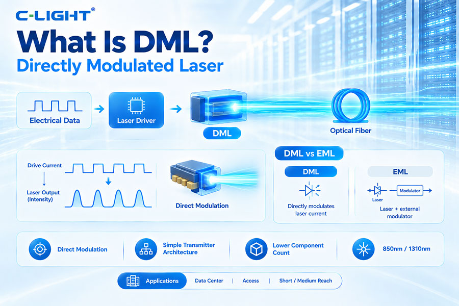
DML, or Directly Modulated Laser, is a semiconductor laser that transmits data by directly varying its drive current. Unlike an externally modulated laser such as EML, DML does not require a separate optical modulator, which can simplify the transmitter architecture and reduce component count.
DML stands for Directly Modulated Laser. In a DML transmitter, the laser's drive current is directly modulated according to the electrical data signal.
The changing drive current causes the laser's optical output power to vary, allowing digital information to be transmitted through optical fiber.
The basic DML transmission process is:
Electrical Data → Laser Driver → DML → Optical Fiber
The driver supplies a modulated current to the laser. The laser converts this electrical variation into a corresponding optical intensity variation.
Direct modulation means that the laser itself is used as the modulation element. The optical output changes directly as the injection current changes.
This differs from external modulation, where a continuous-wave laser generates the optical carrier and a separate modulator changes the optical signal.
A typical DML transmitter can include:
DML laser
Laser driver
Bias-control circuit
Temperature-control elements
Optical coupling components
Monitoring circuitry
The laser driver generates the electrical current required to operate and modulate the DML.
It controls the laser bias and modulation current while maintaining the electrical signal characteristics required for the target data rate.
Laser bias current is the DC current used to keep the semiconductor laser operating around its normal lasing point.
The modulation current is superimposed on this bias current to produce the changing optical output required for data transmission.
When the electrical drive current changes, the carrier density inside the semiconductor laser changes. This changes the laser's optical output intensity.
The resulting optical intensity variations represent the transmitted digital data.
DML technology can be implemented at different wavelengths depending on the laser material and application.
Common communication applications include wavelengths around 850nm for suitable short-reach systems and 1310nm for various data center and access applications.
| Feature | DML | EML |
|---|---|---|
| Modulation method | Directly modulates laser current | Uses external electro-absorption modulation |
| Laser and modulator | Integrated laser modulation | Laser + modulator |
| Complexity | Lower | Higher |
| Bandwidth | More limited at very high speeds | Higher potential |
| Typical use | Short and medium reach | Higher-speed and longer-reach applications |
DML and VCSEL are different laser technologies. DML describes direct modulation of a laser, while VCSEL describes a specific vertical-cavity laser structure.
A VCSEL can also be directly modulated, so these terms describe different characteristics of an optical transmitter.
DML is a laser transmitter technology, while silicon photonics is an integrated photonic platform that can contain waveguides, modulators, couplers, and photodetectors.
A silicon photonics system can use a separate laser source, including a directly modulated or continuously operating laser depending on the architecture.
The main advantages of DML include:
Simple transmitter architecture
Lower component count
Compact size
Potentially lower cost
Low driver and optical complexity
Suitable efficiency for many short-reach applications
DML has several limitations compared with more advanced external-modulation technologies.
Limited modulation bandwidth in some designs
Chirp during direct modulation
Greater sensitivity to some transmission impairments
Less suitable for some very-high-speed or long-reach applications
Wavelength and temperature behavior must be carefully controlled
Laser chirp is a change in the instantaneous optical frequency that occurs when the laser's carrier density changes during direct modulation.
This frequency variation can interact with fiber chromatic dispersion and cause additional signal distortion over longer transmission distances.
Because the laser is directly modulated, its optical frequency can change together with its output intensity.
At longer distances, the interaction between chirp and chromatic dispersion can reduce signal quality and limit transmission performance.
The modulation bandwidth of a DML determines how quickly its optical output can respond to changes in the electrical drive current.
Higher data rates require a laser with sufficient modulation bandwidth and a driver capable of generating the required high-speed current waveform.
DML can support PAM4 in suitable applications, but the laser must provide sufficient linearity, bandwidth, and optical signal quality.
PAM4 has tighter signal margins than NRZ, so transmitter characteristics become increasingly important at higher data rates.
In a PAM4 DML transmitter, the electrical drive signal contains multiple amplitude levels that control the optical output of the laser.
The DML must respond sufficiently linearly to these levels so that the resulting optical waveform preserves the required PAM4 signal quality.
DML is attractive for short-reach applications because its architecture is relatively simple and does not require a separate external optical modulator.
This can reduce component count, size, and implementation complexity.
DML is used in various optical communication applications, including:
Data center optical links
Ethernet optical transceivers
Fiber access systems
Telecommunication equipment
Enterprise networks
Short- and medium-reach optical interconnects
Yes. DML can be used in optical transceivers for suitable short- and medium-reach data center applications.
The exact choice between DML, VCSEL, EML, and silicon photonics depends on the data rate, wavelength, transmission distance, power budget, and required optical performance.
DML can be used in selected 100G optical architectures, particularly where the required bandwidth, reach, and transmitter performance are compatible with the laser design.
Different 100G standards and optical reaches use different transmitter technologies, so DML is not universal across all 100G modules.
DML can be considered for selected 400G architectures, especially shorter-reach applications where the laser bandwidth and linearity are sufficient.
Higher-speed 400G systems may also use EML, VCSEL, or silicon photonics depending on the specific optical architecture.
DML can be used in suitable high-speed architectures, but the requirements become more demanding at 800G.
Bandwidth, linearity, chirp, thermal performance, optical power, and PAM4 signal quality must all be evaluated against the target application.
Temperature affects semiconductor laser characteristics such as threshold current, output power, wavelength, and modulation behavior.
Temperature control and bias management are therefore important for maintaining stable DML transmitter performance.
Bias control maintains the laser at the appropriate operating point. The control circuit can compensate for changes caused by temperature, aging, and other operating conditions.
Stable bias control helps maintain optical output and transmitter performance.
In a two-level optical signal, DML drive conditions influence the optical power difference between high and low states and therefore affect extinction ratio.
The actual extinction-ratio performance depends on the laser, driver, bias current, modulation current, and operating conditions.
RIN, or Relative Intensity Noise, describes fluctuations in optical output power. DML performance can be affected by laser operating conditions, bias current, temperature, and device characteristics.
Low transmitter noise is important for maintaining signal quality in high-speed optical systems.
DML does not define transmission distance by itself. Reach depends on laser bandwidth, chirp, dispersion, optical power, receiver sensitivity, fiber characteristics, modulation format, and system design.
DML is generally more attractive for shorter and medium-reach applications than for the most demanding long-distance links.
| Parameter | DML | EML |
|---|---|---|
| Architecture | Direct laser modulation | Laser + external modulator |
| Components | Fewer | More |
| Chirp | More significant consideration | Generally lower direct-modulation chirp |
| Complexity | Lower | Higher |
| High-speed capability | Application-dependent | Strong |
DML transmitter testing can include several optical and electrical measurements.
Optical output power
Wavelength
Extinction ratio where applicable
Optical modulation amplitude
RIN
Eye diagram
Jitter
BER
Temperature performance
Poor DML performance can result from:
Insufficient modulation bandwidth
Improper bias current
Driver limitations
Excessive temperature
Laser aging
High RIN
Excessive chirp
Optical coupling problems
DML performance can be improved by optimizing both the laser and its driving conditions.
Optimize bias current
Optimize modulation current
Improve driver bandwidth
Control operating temperature
Reduce optical coupling loss
Use suitable equalization
Select a laser matched to the target data rate
DML provides a relatively simple way to generate modulated optical signals without requiring a separate external modulator.
This makes it an important transmitter technology for applications where cost, size, power, and architectural simplicity are major considerations.
DML technology continues to evolve toward higher bandwidth, lower noise, improved linearity, better thermal stability, and greater energy efficiency.
As optical networks move toward higher speeds, DML will remain useful for appropriate short- and medium-reach applications, while EML, silicon photonics, and other advanced transmitter technologies will address applications with more demanding optical requirements.
DML, or Directly Modulated Laser, transmits optical data by directly varying the laser drive current. Its simple architecture eliminates the need for a separate optical modulator, making it compact and efficient for many short- and medium-reach applications. DML performance is influenced by bandwidth, chirp, RIN, bias current, temperature, and linearity, while higher-speed and longer-reach systems may require technologies such as EML or silicon photonics.
For any questions, please contact us by email or WhatsApp.
Email: sales@c-light.com
WhatsApp: +86 132 6656 7067