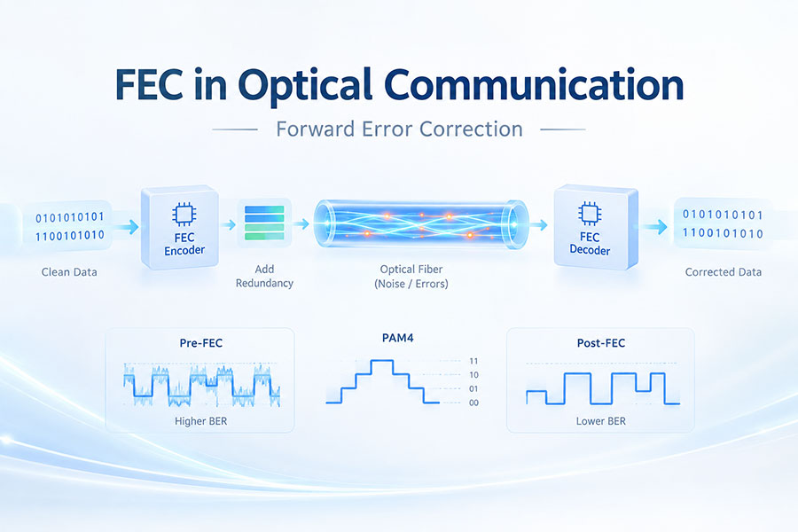
FEC, or Forward Error Correction, is an error-control technology used in optical communication systems to detect and correct certain transmission errors without requiring the receiver to request retransmission. FEC is especially important for high-speed optical networks, including 100G, 400G, 800G, and 1.6T Ethernet systems.
Forward Error Correction is a coding technique that adds redundant information to transmitted data. The receiver uses this additional information to detect and correct certain errors that occur during transmission.
Unlike retransmission-based error recovery, FEC allows the receiver to correct supported errors directly from the received data.
The basic process is:
Original Data → FEC Encoder → Data with Redundancy → Optical Transmission → FEC Decoder → Recovered Data
The transmitter adds carefully calculated parity information to the original data. During transmission, noise and other impairments may introduce errors. The receiver then uses the redundant information to identify and correct errors within the capability of the FEC code.
As data rates increase, maintaining an extremely low raw bit error rate becomes more difficult. High-speed optical links can be affected by noise, optical power limitations, chromatic dispersion, crosstalk, jitter, and other physical impairments.
FEC provides additional error-correction capability and can help a system achieve the required post-FEC error performance.
| Parameter | Meaning |
|---|---|
| Pre-FEC BER | Bit error rate measured before FEC correction |
| Post-FEC BER | Bit error rate after FEC processing |
A link may have a measurable raw BER before FEC while still achieving a much lower error rate after successful FEC correction.
RS-FEC refers to Reed-Solomon Forward Error Correction. Reed-Solomon codes are widely used in high-speed Ethernet systems because they can correct multiple symbol errors within the structure of the encoded data.
Different Ethernet generations and applications use different Reed-Solomon FEC configurations.
Reed-Solomon coding provides strong error-correction performance with a structure well suited to high-speed digital communication.
It is especially useful for PAM4-based Ethernet because PAM4 has smaller signal-level spacing than NRZ and is therefore more sensitive to noise and signal distortion.
PAM4 transmits two bits per symbol using four signal levels. This increases bandwidth efficiency but reduces the amplitude margin between adjacent levels compared with NRZ.
FEC helps compensate for the resulting increase in raw error sensitivity by correcting errors that remain after the physical-layer signal has been received.
With PAM4, the four signal levels are closer together within the available signal range. Noise, jitter, inter-symbol interference, and distortion can therefore cause a received symbol to be interpreted incorrectly.
FEC provides an additional layer of protection against these transmission errors.
FEC can be implemented in different locations depending on the optical networking architecture. It may be handled by the host Ethernet device, optical module DSP, gearbox, or another part of the communication system.
Therefore, an optical transceiver does not automatically imply that FEC is implemented inside the module.
DSP and FEC perform different functions.
DSP primarily performs digital signal processing such as equalization, signal recovery, and compensation. FEC adds redundancy to the data and uses that redundancy at the receiver to detect and correct errors.
In some optical module architectures, FEC-related functions may be integrated into or associated with the DSP, while in others they are implemented elsewhere in the host system.
FEC does not increase the useful payload data rate. Instead, it adds redundant bits or symbols to the transmitted stream.
Because of this overhead, the physical line rate is higher than the net payload rate in systems that use FEC.
FEC overhead refers to the additional data transmitted for error correction. The amount depends on the particular FEC code and system implementation.
This means that the nominal physical signaling rate includes both payload data and error-correction information.
Yes. FEC requires encoding at the transmitter and decoding at the receiver, which introduces processing and buffering latency.
The actual latency depends on the FEC architecture, implementation, code length, hardware design, and operating conditions.
FEC allows the receiver to correct a defined number of errors without retransmission. This increases the error tolerance of the communication system and can improve the effective reliability of the optical link.
However, FEC cannot correct an unlimited number of errors. If the raw error rate becomes too high, the decoder may exceed its correction capability.
When the number or pattern of errors exceeds the correction capability of the FEC code, the decoder may fail to recover the original data correctly.
This can result in uncorrectable codewords, packet errors, link instability, or loss of communication depending on the system architecture.
FEC can effectively increase the error tolerance of a communication system, which may allow the optical link to operate closer to its physical performance limits.
However, FEC does not directly increase optical transmitter power or receiver sensitivity. The achievable reach still depends on the complete optical link budget and applicable transmission standard.
FEC requirements vary by 100G Ethernet standard and optical architecture. Some 100G interfaces use FEC as part of the Ethernet implementation, while other applications may use different configurations.
The exact requirement should be checked against the relevant Ethernet standard and equipment specification.
FEC is widely used in modern 400G Ethernet architectures, particularly where PAM4 signaling is involved.
The specific FEC mode and implementation depend on the applicable Ethernet standard and physical-layer architecture.
Modern 800G Ethernet systems commonly rely on FEC because of the high-speed PAM4 signaling used by many implementations.
FEC helps the system maintain the required post-correction error performance while operating at high aggregate data rates.
As optical interfaces move toward 1.6T, electrical and optical signal margins become increasingly challenging. High-speed PAM4 channels require careful management of noise, jitter, loss, and distortion.
Stronger system-level error correction is therefore important for maintaining reliable operation at these data rates.
FEC gain describes the improvement in error performance provided by the FEC process. It is commonly discussed in terms of the reduction in BER or the additional signal margin enabled by error correction.
Higher FEC gain can allow a communication system to tolerate a higher raw error rate while still achieving the required post-FEC performance.
Coding gain represents the improvement in required signal-to-noise performance made possible by an error-correcting code compared with an uncoded system for a given target error performance.
In optical communication, coding gain is one way to evaluate how effectively an FEC scheme improves system robustness.
The FEC threshold is the maximum raw error performance range within which the FEC decoder can normally achieve the required corrected error rate.
Operating beyond this threshold can significantly increase the probability of uncorrectable errors.
In a transceiver system, FEC may work together with the optical transmitter, receiver, DSP, and host ASIC.
A simplified architecture is:
Host ASIC → FEC Encoding → DSP/SerDes → Optical Transmitter → Fiber → Optical Receiver → DSP/SerDes → FEC Decoding → Host ASIC
The exact signal path varies by transceiver and Ethernet architecture.
| Feature | FEC | Retransmission |
|---|---|---|
| Error recovery | Corrects supported errors at receiver | Requests data again |
| Additional redundancy | Required | Not required in the same way |
| Retransmission traffic | No | Yes |
| Latency | Coding and decoding latency | Additional round-trip delay |
Hard-decision FEC makes decoding decisions from discrete received symbols or bits. Soft-decision FEC uses additional information about the confidence or likelihood of the received values.
Soft-decision approaches can provide stronger coding performance, but they generally require more complex processing and can consume more power.
FEC processing requires additional digital computation. If FEC is implemented within the optical module DSP, this processing contributes to module power consumption.
If FEC is implemented in the host ASIC or another system component, the module itself may not carry the same FEC processing load.
Yes. LPO can operate in systems that use FEC. Removing the traditional DSP from an optical module does not eliminate FEC at the Ethernet system level.
In an LPO architecture, FEC may be handled by the host system while the optical module focuses on linear signal transmission and reception.
Yes. CPO systems can also use FEC as part of the host networking architecture.
Because CPO moves optical conversion closer to the switch ASIC, the optical engine and host ASIC can work together while FEC remains part of the broader data communication system.
FEC performance can be evaluated using measurements such as pre-FEC BER, post-FEC BER, corrected codewords, uncorrectable codewords, and FEC margin.
Testing should be performed under appropriate stress conditions to verify that the communication system maintains the required error performance.
AI data centers rely on large numbers of high-speed optical connections between GPUs, switches, servers, and other networking equipment. A small error rate at each individual link can become significant across a large-scale network.
FEC helps maintain reliable data transmission while supporting the high-speed PAM4 interfaces used in modern AI networking.
The main advantages of FEC include:
Correction of supported transmission errors
Improved link reliability
Reduced dependence on retransmission
Better tolerance of physical-layer impairments
Support for high-speed PAM4 communication
Improved overall system error performance
FEC also introduces trade-offs:
Additional bandwidth overhead
Encoding and decoding latency
Processing complexity
Additional power consumption in some implementations
Limited correction capability
FEC therefore complements good optical and electrical design rather than replacing it.
FEC is a fundamental error-control technology in modern optical communication. By adding redundant information to transmitted data, it allows the receiver to correct certain errors and improve link reliability. FEC is particularly important for PAM4-based 400G, 800G, and 1.6T systems, where signal margins are tighter and raw error performance is more challenging to maintain.
For any questions, please contact us by email or WhatsApp.
Email: sales@c-light.com
WhatsApp: +86 132 6656 7067