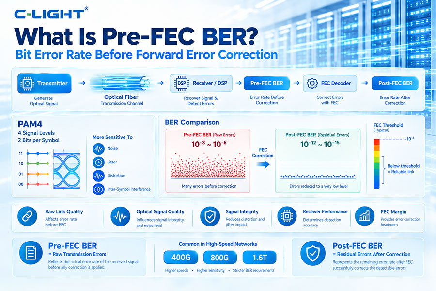
Pre-FEC BER is the Bit Error Rate measured before Forward Error Correction is applied. It represents the raw error performance of a communication link and is an important parameter for evaluating high-speed optical systems, especially PAM4-based 400G, 800G, and 1.6T networks.
Pre-FEC BER means the bit error rate measured at the input to the FEC decoder, before the FEC algorithm corrects transmission errors.
It shows how many errors are present in the received data before error-correction processing is applied.
BER, or Bit Error Rate, is the ratio of incorrectly received bits to the total number of transmitted bits.
A simplified expression is:
BER = Number of Bit Errors / Total Number of Transmitted Bits
A lower BER indicates better transmission performance.
The basic signal path is:
Transmitter → Optical Fiber → Receiver/DSP → Pre-FEC BER → FEC Decoder → Post-FEC BER
The receiver first processes the incoming signal and determines the raw error performance. The FEC decoder then uses redundant coding information to correct errors within its correction capability.
Pre-FEC BER provides a direct indication of the raw condition of the communication channel before error correction.
It helps engineers evaluate optical signal quality, electrical signal integrity, receiver performance, and the margin available before the FEC system is overwhelmed.
| Parameter | Pre-FEC BER | Post-FEC BER |
|---|---|---|
| Measurement position | Before FEC correction | After FEC correction |
| Represents | Raw transmission errors | Residual errors after correction |
| Typical value | Higher | Much lower when FEC operates correctly |
| Main purpose | Evaluate raw link quality | Evaluate final error performance |
FEC adds redundant information to the transmitted data. The receiver uses this information to identify and correct certain errors.
As a result, the BER before FEC can be significantly higher than the residual BER after successful FEC decoding.
FEC does not reduce the physical errors that occur during transmission. Instead, it processes the received data and corrects errors within the capability of the selected code.
Pre-FEC BER therefore describes the condition presented to the FEC decoder.
The FEC threshold is the approximate maximum raw error level at which a particular FEC scheme can still achieve its required corrected error performance.
When pre-FEC BER remains below the applicable threshold, the FEC decoder can generally maintain the required post-FEC performance. When the raw error level exceeds the correction capability, uncorrectable errors may occur.
PAM4 uses four signal levels to transmit two bits per symbol. The smaller spacing between adjacent signal levels makes PAM4 more sensitive to noise, jitter, distortion, and inter-symbol interference than NRZ.
Pre-FEC BER is therefore particularly useful for evaluating the raw performance of PAM4 links.
Any degradation in PAM4 signal quality can increase the probability of symbol and bit errors. Factors such as optical power, electrical loss, jitter, crosstalk, and transmitter linearity can all affect pre-FEC BER.
FEC can correct some of these resulting errors, but the raw error rate must remain within the supported operating range.
High pre-FEC BER can result from many physical-layer problems:
Insufficient optical power
High receiver noise
Excessive laser noise
Electrical channel loss
Jitter
Crosstalk
Inter-symbol interference
Chromatic dispersion
Optical connector or fiber problems
Improper equalization
If the received optical power is too low, the receiver may not have sufficient signal margin to distinguish the transmitted signal from noise.
This can increase raw errors and therefore increase pre-FEC BER.
Receiver sensitivity describes the minimum optical input required to meet a specified performance condition.
Operating close to or below the receiver sensitivity can result in increased pre-FEC BER because the received signal does not provide sufficient margin for reliable detection.
Optical signal quality has a direct impact on the electrical waveform generated by the receiver. Noise, distortion, low optical modulation amplitude, and other impairments can reduce the receiver's ability to distinguish signal levels.
This degradation can appear as a higher pre-FEC BER.
High-speed electrical channels between the host ASIC, PCB, connector, driver, TIA, and optical components can introduce insertion loss, reflections, and crosstalk.
These impairments can distort PAM4 signals and increase the raw error rate before FEC correction.
The eye diagram provides a visual representation of signal quality, while pre-FEC BER provides a numerical indication of raw bit errors.
A degraded eye opening often corresponds to increased error probability, although BER and eye metrics measure different aspects of system performance.
TDECQ is an optical transmitter performance metric commonly used for PAM4 systems. It evaluates transmitter signal quality under a defined measurement methodology.
Pre-FEC BER evaluates the actual error performance of a link, so the two metrics are related to signal quality but are not interchangeable.
In optical systems, lower OSNR means a weaker relationship between the useful optical signal and accumulated optical noise.
Poor OSNR can increase receiver errors and therefore increase pre-FEC BER, although the exact relationship depends on the modulation format, receiver implementation, DSP, and other impairments.
DSP can reduce the impact of several electrical and optical impairments through equalization, clock recovery, dispersion compensation, and other signal-processing functions.
Effective DSP processing can therefore reduce the raw error rate presented to the FEC decoder.
No. Pre-FEC BER is measured before FEC correction. FEC does not change the physical errors already present in the received data before decoding.
FEC improves the corrected or post-FEC error performance by detecting and correcting supported errors.
There is no single pre-FEC BER value that applies to every optical system. The acceptable range depends on the FEC architecture, modulation format, Ethernet standard, transceiver design, and target post-FEC performance.
The correct value should therefore be evaluated against the specification of the complete link.
Pre-FEC BER helps engineers understand the physical-layer margin of a communication link before error correction hides some of the underlying errors.
This makes it useful for transceiver validation, system qualification, troubleshooting, and margin testing.
Pre-FEC BER can be measured by transmitting a known test pattern and comparing the received data before FEC correction with the expected pattern.
The measurement may be performed using dedicated test equipment, host-side diagnostics, or DSP and transceiver monitoring functions when supported.
BER testing can use standardized or controlled pseudo-random data patterns depending on the interface and test equipment.
Common approaches include PRBS-based patterns, which provide repeatable and stressful test conditions for evaluating high-speed electrical and optical links.
The required measurement time depends on the target BER and test objective. Very low error rates require long observation periods to obtain statistically meaningful results.
Testing should therefore use an appropriate sample size and measurement duration for the required confidence level.
When pre-FEC BER exceeds the correction capability of the FEC scheme, the decoder may produce uncorrectable codewords or packets.
This can lead to degraded network performance, packet loss, link instability, or complete link failure depending on the system.
Reducing pre-FEC BER requires improving the underlying physical link.
Optimize transmitter optical power
Improve receiver performance
Reduce electrical channel loss
Improve signal equalization
Control connector and fiber losses
Reduce crosstalk and jitter
Improve thermal stability
Use suitable optical components
400G optical systems commonly use PAM4 signaling and multiple high-speed lanes. Pre-FEC BER is used to evaluate the raw performance of these lanes before FEC correction.
The acceptable pre-FEC error level depends on the specific Ethernet architecture and FEC implementation.
800G systems commonly use multiple 100G-class PAM4 lanes. Because the lane speeds are high and signal margins are tight, pre-FEC BER is an important diagnostic parameter.
It can help identify degradation caused by optics, electrical channels, host interfaces, or system-level signal integrity.
1.6T-class systems use even higher-speed electrical and optical lanes, increasing the importance of raw error monitoring.
Pre-FEC BER can provide an early indication of whether a high-speed link is operating within the error tolerance required by the FEC architecture.
Optical power measures the strength of the optical signal, while pre-FEC BER measures the resulting bit error performance of the communication link.
Adequate optical power does not always guarantee a low BER because other impairments can still degrade the signal.
AI data centers use large numbers of high-speed optical links, so small performance variations can affect many connections at scale.
Monitoring pre-FEC BER can help identify degrading links before errors exceed the correction capability of the FEC system.
A rising pre-FEC BER can indicate degradation in the optical or electrical path even when the post-FEC link still appears healthy.
Engineers can use the trend to investigate fiber connections, optical power, temperature, host SerDes behavior, signal integrity, and other possible causes.
As optical interfaces move toward 800G and 1.6T, real-time monitoring of raw link performance becomes increasingly valuable.
Integrated DSP diagnostics, host telemetry, and advanced optical monitoring can provide more detailed visibility into pre-FEC performance and help identify links approaching their error margins.
Pre-FEC BER is the raw bit error rate measured before Forward Error Correction. It provides an important view of the physical-layer condition of an optical communication link and is particularly useful for PAM4-based 400G, 800G, and 1.6T systems. Monitoring pre-FEC BER helps engineers evaluate signal quality, identify link degradation, and ensure that the raw error rate remains within the correction capability of the FEC system.
For any questions, please contact us by email or WhatsApp.
Email: sales@c-light.com
WhatsApp: +86 132 6656 7067