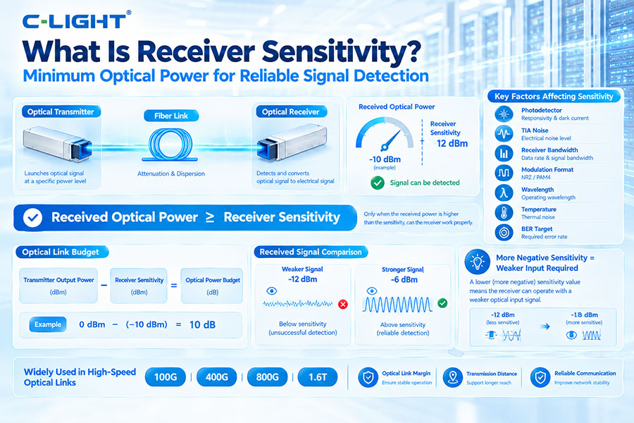
Receiver sensitivity is the minimum optical power a receiver requires to achieve a specified performance level under defined operating conditions. It is one of the most important parameters in optical transceivers because it directly affects optical link margin, transmission distance, and overall communication reliability.
Receiver sensitivity describes how weak an optical signal can be while still allowing the receiver to operate within a specified performance target.
A receiver with better sensitivity can correctly detect a weaker optical signal than one with poorer sensitivity.
Optical receiver sensitivity is normally expressed in dBm.
Because optical receiver power levels are often very low, negative dBm values are common. A more negative sensitivity value generally represents a receiver capable of operating with a weaker optical input.
The basic concept is:
Received Optical Power ≥ Receiver Sensitivity
When the received optical power falls below the receiver sensitivity under the specified test conditions, the receiver may no longer maintain the required BER or other performance target.
Receiver sensitivity determines how much optical signal the receiver needs to recover data reliably. It is therefore an important factor when designing fiber links, selecting optical transceivers, and calculating link budgets.
A receiver with better sensitivity can provide greater tolerance to optical losses when other parameters remain comparable.
| Parameter | Receiver Sensitivity | Received Optical Power |
|---|---|---|
| Meaning | Minimum optical input required for specified performance | Actual optical power arriving at the receiver |
| Type | Receiver specification | Link operating value |
| Unit | dBm | dBm |
There is no single sensitivity value that is considered good for every optical transceiver. The required sensitivity depends on the data rate, modulation format, receiver architecture, wavelength, transmission distance, BER target, and applicable standard.
The correct value should always be evaluated together with the transmitter output power and other link parameters.
Transmitter output power describes the optical power launched into the fiber, while receiver sensitivity describes the minimum optical input required at the receiving side.
The difference between these two values is an important part of the available optical power budget.
A simplified optical link budget can be represented as:
Optical Power Budget = Transmitter Output Power − Receiver Sensitivity
For example, if a transmitter launches 0 dBm and the receiver sensitivity is -10 dBm, the simplified available optical budget is 10 dB.
The actual link design must then account for fiber attenuation, connectors, splices, passive components, and an appropriate engineering margin.
Consider two receivers with sensitivities of -8 dBm and -12 dBm. The second receiver can operate with a weaker optical signal under the specified test condition.
Therefore, the -12 dBm receiver has better sensitivity in this example.
As a signal travels through optical fiber, its power decreases because of fiber attenuation and other optical losses.
A receiver with better sensitivity can tolerate a lower received optical power, which can provide more link margin and potentially support a longer transmission distance when other conditions are unchanged.
Receiver sensitivity depends on many parameters:
Photodetector performance
TIA noise
Receiver bandwidth
Signal modulation format
Optical wavelength
Temperature
BER target
FEC architecture
DSP performance
The photodetector converts incoming optical power into an electrical current. Its responsivity, bandwidth, dark current, and noise characteristics can affect receiver performance.
Common photodetector technologies include PIN photodiodes and avalanche photodiodes.
The transimpedance amplifier, or TIA, converts the photodetector current into a usable electrical voltage signal.
TIA noise and bandwidth directly affect the quality of the recovered electrical signal and therefore influence receiver sensitivity.
In DSP-based optical systems, digital signal processing can compensate for certain signal impairments after optical detection.
Equalization, clock recovery, dispersion compensation, and other processing functions can improve signal recovery, although the specified receiver sensitivity still depends on the complete receiver implementation and measurement conditions.
PAM4 uses four amplitude levels to transmit two bits per symbol. The smaller spacing between adjacent levels results in lower signal margin compared with two-level NRZ signaling.
This makes high-speed PAM4 receivers more sensitive to noise, distortion, jitter, and other impairments.
400G optical systems commonly use PAM4 signaling and multiple high-speed lanes. The receiver must detect small differences between multiple signal levels while maintaining the required error performance.
Receiver sensitivity is therefore an important specification in 400G optical transceivers.
800G systems operate at even higher aggregate and lane speeds. Noise, electrical loss, optical distortion, and other impairments become increasingly important.
Receiver sensitivity helps define how much optical power the receiver needs under the specified operating conditions.
1.6T-class systems require extremely high-speed electrical and optical processing. Maintaining sufficient receiver margin becomes more challenging as lane rates increase.
Receiver sensitivity remains an important metric when evaluating the performance of next-generation optical receivers.
| Parameter | Receiver Sensitivity | Receiver Overload |
|---|---|---|
| Meaning | Minimum acceptable optical input | Maximum optical input before performance degrades |
| Lower limit | Defines weak-signal operation | Not applicable |
| Upper limit | Not applicable | Defines excessive optical input |
Receiver overload power is the maximum optical input power at which the receiver can maintain its specified performance.
This means an optical receiver has both a lower operating boundary defined by sensitivity and, in many specifications, an upper boundary defined by overload.
Receiver dynamic range is the usable range between the minimum optical input associated with receiver sensitivity and the maximum optical input associated with receiver overload.
A wider dynamic range gives the receiver more tolerance to changes in received optical power.
Link margin is the difference between the available received optical power and the minimum power required by the receiver.
A simplified expression is:
Link Margin = Received Optical Power − Receiver Sensitivity
A positive margin indicates that the received signal is above the specified sensitivity threshold.
Suppose the receiver sensitivity is -12 dBm and the actual received optical power is -6 dBm.
The simplified link margin is:
-6 dBm − (-12 dBm) = 6 dB
This means the received optical signal has 6dB of power above the sensitivity value under the stated conditions.
Real optical links can experience changes caused by temperature, connector aging, fiber repairs, component variation, and other operating conditions.
Adding an engineering margin helps prevent a link from operating too close to the receiver sensitivity limit.
Temperature can influence photodetector characteristics, TIA behavior, laser output, and other electronic components.
As a result, receiver sensitivity may vary across the operating temperature range, and optical modules are normally tested under defined temperature conditions.
Fiber loss reduces the optical power arriving at the receiver. The receiver sensitivity determines whether the remaining signal is still strong enough for reliable data recovery.
Longer links and links with greater passive loss therefore require sufficient transmitter power and receiver sensitivity.
Receiver sensitivity is a characteristic of the receiver, while optical power budget represents the total amount of loss that the transmitter and receiver combination can tolerate.
Sensitivity is therefore one of the key inputs used to calculate the available link budget.
Receiver sensitivity is tested by reducing the optical input power while monitoring the receiver's performance under defined conditions.
The sensitivity point is reached when the receiver meets the specified performance threshold at the specified input power.
Sensitivity testing can involve:
Input optical power
BER
Data rate
Wavelength
Temperature
Modulation format
Test pattern
FEC condition
The exact test method depends on the relevant optical standard or product specification.
In systems that use FEC, sensitivity can be evaluated using different error-performance definitions. A pre-FEC condition evaluates the raw error performance before FEC correction, while a post-FEC condition evaluates the residual performance after correction.
Therefore, sensitivity specifications must always be interpreted together with the stated BER and FEC conditions.
Long-distance optical links accumulate fiber attenuation and losses from connectors, splices, filters, amplifiers, ROADMs, and other components.
Receiver sensitivity determines how weak the optical signal can become before the receiver can no longer meet the required performance.
Receiver sensitivity focuses on the minimum optical input required under a defined performance condition, while OSNR describes the relationship between optical signal power and optical noise.
A receiver may have sufficient total optical power but still experience poor performance when optical noise becomes too high.
RIN, or Relative Intensity Noise, describes fluctuations in laser optical power. Excessive RIN can increase noise at the receiver and affect overall link performance.
Therefore, receiver sensitivity should be considered together with transmitter noise and other signal-quality parameters.
Receiver sensitivity is normally specified against a defined performance target, often involving BER or an equivalent error metric.
Changing the target BER can change the measured sensitivity value because the receiver may require more optical power to achieve a stricter error-performance requirement.
As optical systems move toward higher data rates, receiver sensitivity will remain an important parameter for evaluating optical module performance.
Future receivers will continue to focus on lower noise, higher bandwidth, improved linearity, more efficient signal processing, and better performance across wider operating conditions.
Receiver sensitivity is the minimum optical power required for a receiver to meet a specified performance target. Expressed in dBm, it is a key parameter for optical transceivers, link budgets, and transmission-distance planning. Receiver sensitivity is influenced by photodetectors, TIAs, DSP, modulation, noise, temperature, and BER requirements, and should always be evaluated together with transmitter power, receiver overload, optical losses, and available link margin.
For any questions, please contact us by email or WhatsApp.
Email: sales@c-light.com
WhatsApp: +86 132 6656 7067